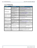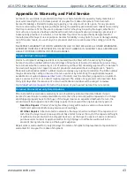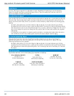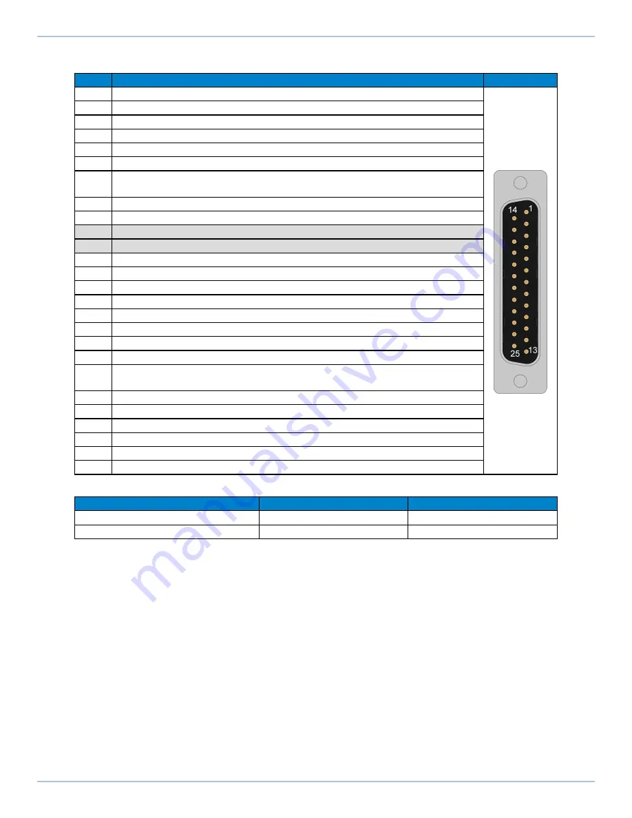
Table 3-1:
Motor and Feedback Connector Pinouts
Pin
Description
Connector
Case
Cable Shield
1
SIN1+ (Encoder Sine 1+)
2
COS1+ (Encoder Cosine 1+)
3
5V Common Ground
4
SIN2+ (Encoder Sine 2+)
5
COS2+ (Encoder Cosine 2+)
6
+/CW LMT (The limit signal that shows the maximum permitted machine
travel in positive or clockwise encoder counts.)
7
MRK+ (Encoder )
8
Encoder 5V Supply Input
9
Reserved
10
Reserved
11
Frame Ground
12
Motor +
13
Motor +
14
SIN1- (Encoder Sine 1-)
15
COS1- (Encoder Cosine 1-)
16
5V Common Ground
17
SIN2- (Encoder Sine 2-)
18
COS2- (Encoder Cosine 2-)
19
-/CCW LMT (The limit signal that shows the maximum permitted machine
travel in negative or counterclockwise encoder counts.)
20
MRK- (Encoder Marker-)
21
5V Common Ground
22
5V Common Ground
23
Frame Ground
24
Motor -
25
Motor -
Table 3-2:
Mating Connector Part Numbers for the Motor and Feedback Connector
Mating Connector
Aerotech P/N
Third Party P/N
25-Socket D-Connector
ECK00300
FCI DB25S064TLF
Backshell
ECK00656
Amphenol 17E-1726-2
AGV-SPO Hardware Manual
3.1. Motor and Feedback Connectors
www.aerotech.com
33
Содержание AGV-SPO Series
Страница 1: ...Revision 2 00 AGV SPO Single Pivot Point Galvo Scanner HARDWARE MANUAL...
Страница 6: ...This page intentionally left blank List of Tables AGV SPO Hardware Manual 6 www aerotech com...
Страница 12: ...This page intentionally left blank Laser Shutter AGV SPO Hardware Manual 12 www aerotech com...
Страница 14: ...This page intentionally left blank EU Declaration of Incorporation AGV SPO Hardware Manual 14 www aerotech com...
Страница 16: ...Figure 1 2 Standard AGV SPO Chapter 1 Overview AGV SPO Hardware Manual 16 www aerotech com...
Страница 30: ...This page intentionally left blank 2 6 Water Requirements AGV SPO Hardware Manual 30 www aerotech com...
Страница 38: ...This page intentionally left blank 3 5 Feedback Phasing AGV SPO Hardware Manual 38 www aerotech com...
Страница 46: ...This page intentionally left blank Appendix B Revision History AGV SPO Hardware Manual 46 www aerotech com...


