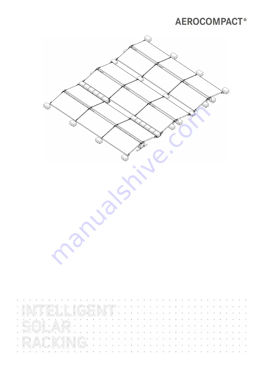
CompactFLAT
S10plus
Assembly Instructions
Version: 04Language: English | Original language: GermanOriginal installation instructions
Important! Read carefully before installation!
Страница 1: ...CompactFLAT S10plus Assembly Instructions Version 04 Language English Original language German Original installation instructions Important Read carefully before installation...
Страница 2: ...ions in another lan guage are a translation of the assembly instructions in German The assembly instructions are protected by copyright Without written permission from AEROCOMPACT the assembly instruc...
Страница 3: ...cessories 12 Variations of CompactFLAT S10plus 12 Assembly 13 Installation Instructions for Gravel Roofs 13 Gravel Depth up to 2 5 in 13 Gravel Depth 2 5 in to 4 in 13 Gravel Depth greater than 4 inch...
Страница 4: ...sition the Mechanical Attachments 28 Installing the mechanical attachments 29 Bonding and Grounding 29 Maintenance 31 Complete System 31 Fittings 31 Dismantling 32 Disassemble components 32 Dismantle...
Страница 5: ...tions symbols terms and abbreviations are used The following symbols indicate notes which are not relevant to safety but which make working with the assembly instructions easier Requirements for an ac...
Страница 6: ...y other use of the CompactFLAT system is considered improper Liability Warranty Guarantee These assembly instructions and the project report supplied with the product are integral parts of the product...
Страница 7: ...the corresponding fasteners on the respective roof in terms of warranties nor for the professional execution Errors and damage as well as limited or insufficient functionality of the system due to in...
Страница 8: ...face Define walking routes and secure them with load distribution measures On roofing or roof structures that do not have sufficient load bearing capacity e g thin sheets corrugated fibre cement alway...
Страница 9: ...falling objects Where this does not succeed affected areas must be closed to the public Persons involved in the construction project must wear safety helmets Personal protective equipment PPE Personal...
Страница 10: ...p CLE10 2 Connector long with without roof protection pad S10 CNL PP S10 CNL Connector short with without roof protection pad S10 CNS PP S10 CNS 3 Middle bracket with without roof protection pad S10 M...
Страница 11: ...st tray 3 Long ballast tray BT 1800 BT 2050 BT 2300 4 Short ballast tray BT 880 5 Roof protection pad for ballast blocks and ballast trays PP200 80 Alpine supports 1 Alpine front support S10FS al 2 Ce...
Страница 12: ...tion to mechanical attachment AC200 AC80 2 Cable conduit CP 430 CP 620 CP 840 3 Bracket for cable conduit BR CP Variations of CompactFLAT S10plus Compact FLAT S10plus 464 mm distance 8 18 internal sha...
Страница 13: ...he protective fleece If possible and if properly calculated with the help of design professionals use the gravel as ballast in the ballast trays or distribute it evenly on the roof again Gravel Depth...
Страница 14: ...S10plus Assembly www aerocompact com 14 Pre install the end clamps or mid clamps to the front brackets middle brackets and connector brackets as needed...
Страница 15: ...he length of the array and mark the line Measure the width of the array and mark the line Place the front brackets middle brackets and connector brackets in the array field Edge rows place front brack...
Страница 16: ...can be attached to the module with the cable tie clip CLP M Install the first module row Weigh down the front brackets with ballast blocks Place the module on the front brackets and middle brackets Al...
Страница 17: ...next module Tighten the screws of the mid clamps of the previous module with 15 Nm or 11 ft lbs Lastly add end clamps to each of the middle brackets Tighten the screws to 15 Nm or 11 ft lbs Install t...
Страница 18: ...he middle brackets and connector brackets Align each module with the marks on the middle brackets connector brackets Tighten the screws of the end clamps with 15 Nm or 11 ft lbs For stronger bonding a...
Страница 19: ...erally out of the rail Installing modules with alpine supports optional Above a certain snow load additional support brackets alpine brackets are required at the middle of the module frame The plannin...
Страница 20: ...ge 16 The alpine supports optional are mounted in parallel with the modules Place an additional middle bracket and a connector bracket at the center of each module frame Place the module on the center...
Страница 21: ...S10plus Assembly www aerocompact com 21 Place and align next module Tighten the screws of the end clamps with 15 Nm or 11 ft lbs Tighten the screws of the mid clamps to 15 Nm or 11 ft lbs...
Страница 22: ...stall remaining modules row by row as described Position a front alpine support in the middle of the module frame of both the front and back rows Make sure that the end clamps are flush with the modul...
Страница 23: ...support Install the microinverter on the microinverter bracket according to the manufacturer s specifications Place installed microinverter on the bracket connector bracket or support below the module...
Страница 24: ...be minimal but the PV system will be prone to higher sliding values Option 1 Ballasting directly on the front brackets middle brackets or connector brackets With this ballasting option the ballast bl...
Страница 25: ...ing documents for the exact number and position of the short ballast trays Installing the short ballast tray Position building protection mats underneath and to the right and left edge of the ballast...
Страница 26: ...mm 4 roof protection pads per ballast tray Length 2300 mm 5 roof protection pads per ballast tray When positioning the protection pads make sure that the drain holes at the bottom of the ballast tray...
Страница 27: ...cs screw Installing cable pipe assembly optional The cable pipes can be installed at the edges or interior of the module field Depending on the situation the cable pipe is installed through the long b...
Страница 28: ...e screws to 15 Nm or 11 ft lbs Attach the cable pipe to the brackets Attach the plastic caps to the end of the cable pipe Mechanical Attachments Note the number and positions of the mechanical attachm...
Страница 29: ...s The mechanical attachment can be installed together with the wind deflectors and or ballast trays Install the angle connection from the mechanical attachment to the connector bracket bracket Screw o...
Страница 30: ...a module field at a starting bracket connector bracket with an ALtracs screw STS8x16 Loosen and remove screw Attach washer and certified grounding lug in the order shown with the screw Tighten the sc...
Страница 31: ...nance items once a year A test of the system is necessary after severe weather events e g wind storm snow hail etc as well as after extreme events such as a hurricane or earthquake Complete System Che...
Страница 32: ...com 32 DISMANTLING Disassemble components Disassembling the system Carry out the assembly steps in reverse order Dismantle clamps Completely unscrew the screw on the clamp If clamps are re installed M...
Страница 33: ...NDIX Declaration of Conformity S10plus 21 Manufacturer AEROCOMPACT To the declaration of per formance Designation CompactFLAT S10plus East West sys tem for flat roofs Identification code S10plus Appli...