22
23
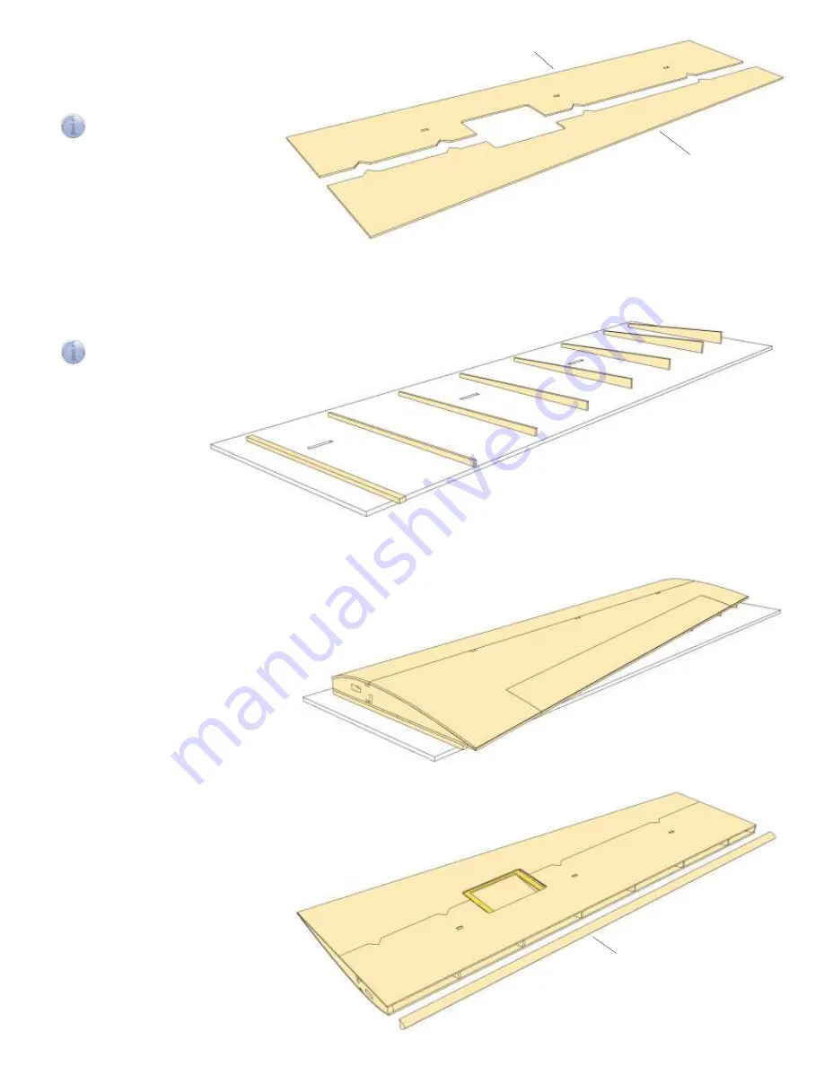
Glue together lower wing sheeting F47, F48 (L/R) and secure with tape
until dry.
Insert supports H3 to H10 into jig at rib positions.
The use of supports H3 to H10 guarantees correct amount of washout in outer wing
panel.
Note:
Picture shows arrangement for right wing panel. Turn jig upside down and
reverse order of supports for left wing panel.
F47 L/R
F48 L/R
H3
H4
H5
H6
H7
H8
H9
H10
Optional:
If the model is to be
equipped with ailerons, insert aileron
servo lead now and secure in servo bay
with tape.
24
Slightly bevel rear edge of upper wing sheeting to establish a good contact surface for gluing.
Align lower wing sheeting with tabs on main spar and place sheeting panel on spars and ribs.
Check for correct fit, then glue in place and briefly press onto a flat surface.
Remove any residual glue from inner edge
of servo frame.
At rear edge of wing secure upper an lower
wing sheeting with two strips F11 and
clamps, then place outer wing panel on
supports. Make sure front edge of wing
sheeting is flus with front end of supports.
Weigh down wing panel evenly on supports
and let dry.
F49
25
Sand sheeting material flush with front
end of ribs. Glue in place leading edge
F49 flush with upper sheeting and
secure to wing with tape.
26
27
Glue wing tip F54 to end rib and secure with pins.
Carefully sand completed outer wing panel and sand
contour of wing tip flush with upper and lower sheeting.
Then chamfer edge of wing tip.
Build up opposite wing panel accordingly.
Install servo tray F50 in wing and drill servo frame F44
with 1.5 mm.
When wing is completed, attach servo tray to wing with
screws F52.
F50
F54
F55
F53
F50
F51
F51
Optional: Installing Ailerons
28
29
Cut out aileron along engraved lines and carefully sand sheeting
material and ribs flush with spars. Sand front end of aileron flush
with F41, glue aileron leading edge F55 (3 mm balsa) to F41
and bevel for sufficient control throw.
Place wing upside down on building board and replace aileron
in cut-out.
Make up control linkage from clevis F57 and threaded rod F56,
cut to length and make a Z-bend at free end. Attach control
linkage to servo arm.
Use control linkage to mark position of control horn on aileron.
Use file or razor saw to create slot for control horn F53 in
aileron and glue control horn in place.
For aileron control use servos with a maximum thickness of
8 to 10 mm.
For standard 10 mm wing servos cut to length four 20 mm
servo mounts F51 (5×3 mm spruce). Cut off bottom servo
mounting flange, align servo with servo arm centred in slot
of servo tray F50, hold in place and glue servo mounts to
tray with a drop of white glue or medium CA.
cut off
i
i
F41
Содержание LT 200 Flex
Страница 1: ...aero naut Order No 1328 00 Flex...


