2 2 / 1 0 – 5 3 3 0 6 0 1 _ 0 1
T r a n s l a t i o n o f O r i g i n a l i n s t r u c t i o n s
w w w . a e r m e c . c o m
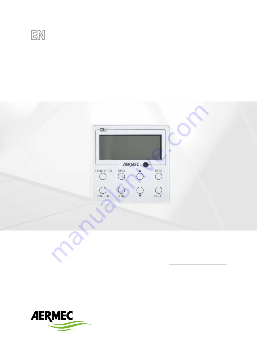
User manual
WIRED CONTROLLER
WRCB
Страница 1: ...2 2 1 0 5 3 3 0 6 0 1 _ 0 1 T r a n s l a t i o n o f O r i g i n a l i n s t r u c t i o n s w w w a e r m e c c o m User manual WIRED CONTROLLER WRCB ...
Страница 2: ... for further details Illegal dumping of the product by the user entails the application of administrative sanctions provided by law Dear customer Thank you for choosing an Aermec product It is the fruit of many years of experience and special design studies and has been made of the highest grade materials and with cutting edge technology In addition all our products bear the CE mark indicating tha...
Страница 3: ...ng Setting if available p 10 Sleep Setting p 11 Turbo Setting p 12 Energy Saving Function Setting p 13 X fan Setting p 14 Quiet Function Setting p 15 Absent Setting p 16 I Demand Setting p 17 WiFi Function Setting p 18 Other Functions p 18 5 Installation and Dismantlement p 19 Connection of the Signal Line of the Wired Controller p 19 Installation of the Wired Controller p 19 Dismantlement of the ...
Страница 4: ... to the owner s manual of unit The setting of such unavailable function will not affect unit s operation The wired controller is universal The remote receiver is either in the indoor unit or in the wired controller Please refer to the specific models As for some indoor units connected with the wired controller if use the remote controller whose set temperature is adjustable under auto mode the wir...
Страница 5: ...5 WIRED CONTROLLER WRCB 2 1 SYMBOLS ON LCD 2 1 1 Outside View of the Wired Controller Fig 1 Outside View of the Wired Controller ...
Страница 6: ... set 13 Child lock Child lock status display when child lock function is set 14 Up Down Swing Setting Display when up and down swing function is set 15 UNAVAILABLE UNAVAILABLE 16 Fan speed The fan speed set currently including auto low medium low medium medium high high and turbo 17 No card No card in gate control system 18 Left Right Swing Setting Display when left and right swing function is s 1...
Страница 7: ...nder off state of the unit press them at the same time for 5s to enter the lock state in which case any other buttons won t respond the press Repress them for 5s to quit this state 4 7 MODE Under OFF state the Celsius and Fahrenheit scales can be switched by pressing MODE and for 5s 2 5 TIMER FUNCTION Under OFF state it is available to go to the commissioning status by pressing FUNCTION and TIMER ...
Страница 8: ...4 3 TEMPERATURE SETTING Press or to increase decrease the preset temperature If press either of them continuously the temperature will be increased or decreased by 1 C 1 F every 0 5s as shown in Fig 6 In the Cooling Dry Fan or Heating mode the temperature setting range is 16 C 30 C 61 F 86 F In the Auto mode the setting temperature is unadjustable Note If the wired controller receives the signals ...
Страница 9: ... the setting Timer off setting press Timer if LCD won t display xx x hour and then it means the timer setting is canceled Timer off setting under the ON state of the unit is shown as Fig 8 Fig 8 Timer off Setting under the ON State of the Unit Wi Fi Wi Fi Wi Fi Wi Fi Wi Fi Turn on the unit without setting timer Press TIMER button to set Press or button to adjust time Press SWING ENTER to finish ti...
Страница 10: ...o activate the swing function In this case will blink After that press SWING ENTER to make a confirmation After that press SWING ENTER to make a confirmation Swing Off When the Swing function is on press FUNCTION to enter the Swing setting interface with blinking After that press SWING ENTER to cancel this function Swing setting is shown as Fig 9 Fig 9 Swing Setting Wi Fi Wi Fi Wi Fi Wi Fi Wi Fi 1...
Страница 11: ...ion is activated press FUNCTION to enter the Sleep setting interface After that press SWING ENTER to can this function Sleep setting is shown as Fig 10 Fig 10 Sleep Setting Wi Fi Wi Fi Wi Fi Wi Fi Wi Fi Turn on the unit without turning on sleep Press SWING ENTER button to turn on sleep Press FUNCTION button into sleep Press FUNCTION button into sleep Press SWING ENTER button to cancel sleep ...
Страница 12: ...s SWING ENTER to confirm the setting When the Turbo function is activated press FUNCTION to enter the Turbo setting interface and then press SWING ENTER to cancel this function Turbo function setting is as shown in Fig 11 Fig 11 Turbo Setting Wi Fi Wi Fi Wi Fi Wi Fi Wi Fi Turn on the unit without turning on turbo Press FUNCTION button into turbo state Press SWING ENTER to turn on turbo function Pr...
Страница 13: ...y saving setting mode press MODE button to switch the energy saving setting for COOL or HEAT mode Cancel energy saving function If energy saving function has been set press FUNCTION button on the panel to select SAVE When SAVE icon flashes if you press SWING ENTER button without pressing or button energy saving function will be canceled if you press SWING ENTER button after pressing or button ener...
Страница 14: ...ting is as shown in Fig 13 Fig 13 X fan Setting Wi Fi Wi Fi Wi Fi Wi Fi Wi Fi Turn on the unit without turning on X fan function Press FUNCTION button into X fan state Press SWING ENTER button to turn on X fan function Press FUNCTION button into X fan state Press SWING ENTER button to turn off X fan function Note 1 When the X FAN function is activated if turning off the unit by pressing ON OFF or ...
Страница 15: ...tton on the panel to select Quiet function option When Quiet or Auto quiet flashes if you press SWING ENTER button without pressing or button quiet function will be canceled if you press SWING ENTER button after pressing or button quiet function will be activated Fig 14 Setting of Quiet Function Wi Fi Wi Fi Wi Fi Wi Fi Wi Fi Wi Fi Turn on the unit with the Quiet function deactivated Press FUNCTION...
Страница 16: ...in 8 C 46 F In this case temperature setting and fan speed setting are shielded 3 This function will be cancelled when switching modes 4 This function and sleep function cannot be on simultaneously If Absent function is set firstly and then sleep quiet function is set Absent function will be cancelled while sleep function will be valid and vice versa Fig 15 Absent Setting Wi Fi Wi Fi Wi Fi Wi Fi W...
Страница 17: ...is function has been set set temperature is displayed in SE In this case temperature setting and fan speed setting are shielded 3 This function will be cancelled when switching modes 4 This function and sleep function cannot be on simultaneously If I demand function is set firstly and then sleep quiet function is set I demand function will be cancelled while sleep function will be valid and vice v...
Страница 18: ... resume its original running state upon power recovery Memory contents ON OFF Mode set temperature set fan speed and Lock function 3 SELECTION OF THE TEMPERATURE SENSOR Under OFF state of the unit press both FUNCTION and TIMER for five seconds to go the commissioning status Under this status adjust the display in the temperature dis play area to 00 through the button MODE and then adjust the optio...
Страница 19: ...ire CN2 and CN3 which are used for connecting the CC2 Accessory if desired There is no sequence for these two needle stands You can connect one or two needle stand s basing on the requirement Fig 18 shows the installation steps of the wired controller please pay attention to the following notes 1 Prior to the installation please firstly cut off the power supply of the wire buried in the installati...
Страница 20: ...gram after the connection wire and the patch cord have been connected connect the terminal 2 of connection wire and the terminal 4 of patch cord WRCB Control Panel can be connected to the CC2 Accessor Fig 22 WRCB n 1 WRCB n 2 WRCB n 3 CC2 B2 A2 B3 A3 F1 F2 G1 G2 WRCB n 36 Termination Resistance CN3 CN2 CN1 Terminals Twisted cable KEY Connection can be made with the aid of the IC 2P accessory Indoo...
Страница 21: ...board of wired controllerWRCB As for the last n wired controller in the control system the 1 bit and the 2 bit of the DIP switch should be manually pulled to position on and position off respectively The DIP switches of other wired controllers should be kept at the initial ex factory status 1 bit and 2 bit are set at position off ATTENTION Please pay special attention to the following notes during...
Страница 22: ...fter having configured the addresses of the indoor unit via the wired control panel you can proceed with connection via the CC2 centralised control by referring to its user manual 7 SET THE INDOOR UNIT ADDRESS BMS It is necessary to set the value of the serial address to the unit as follows Press and hold the FUNCTION and MODE buttons simultaneously for 5 seconds With keys and select the value of ...
Страница 23: ...r voltage protection PH Overload protection E8 Compressor phase current sensing circuit error U1 Whole unit over current protection E5 Compressor demagnetization protection HE Over phase current protection P5 PFC protection Hc Compressor desynch H7 IPMTemperature Protection P8 IPM Current protection H5 Overload protection L9 Compressorphaseloss reversal protection Ld System charge shortage or bloc...
Страница 24: ...A e r m e c S p A V i a R o m a 9 9 6 3 7 0 4 0 B e v i l a c q u a V R I t a l y P h o n e 3 9 0 4 4 2 6 3 3 1 1 1 F a x 3 9 0 4 4 2 9 3 5 7 7 s a l e s a e r m e c c o m w w w a e r m e c c o m ...