


5
- Faults that may arise from irregularities in the electrical supply where the device is installed.
- Damage caused by failure to make drainage pipe and to be corrosion inside the device.
- Damage that may be caused by the corrosive and acidic effect of the environment in which the device will operate.
- Damages caused by foreign materials forgotten in the device or fan motor.
- Damage caused by not using flexible connection in channel connections.
- Damages caused by failure to observe the points specified in this user manual.
AERA heat recovery devices do not have any parts replacement or repair work to be performed by the user other than cleaning
and eye inspection. Users should contact the AERA company for faults detected during operation or maintenance.
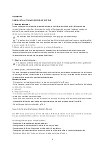
1.3 Regulations – Guidelines
If the product is installed correctly and used to its intended purpose, it conforms to all applicable CE standards at its date of
manufacture. The AERA EVO-R ventilation units in this series are compliant with Eco-Design 2018.
1.4 Receipt
The delivery contains one of the following unit types:
Please check delivery immediately on receipt for accuracy and damage. If damaged, please notify carrier immediately.
In case of delayed notification, any possible claim may be void.
1
.
5 Storage
When storing for a prolonged time the following steps are to be taken to avoid damaging influences:
Protection by dry, air- dustproof packing (plastic bags with drying agent and moisture indicators). The storage place must be
water-protected, vibration-free and free of temperature variations. (Ambient temperature limit, min/max, 0°C/ +40°C) Damages
due to improper transportation, storage or putting into operation are not covered by warranty.
1.6 Transport
The transport of the devices must be done with carefully. All manufactured devices are shipped from the factory after all tests and
controls have been made before shipment.
The transport must be carried out by trained and experienced personnel and the necessary safety precautions should be taken
to prevent overturning and slipping of the device. During transport of the devices it should be ensured that the weight is evenly
distributed over the four corners.
Danger due to overhead loads – risk of grave injuries or death!
- Never stand beneath suspended loads, since there is always a risk that the lifting gear, tackle, ropes or slings are faulty or
damaged.
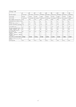
Unit
EVO-15R
EVO-20R
EVO-30R
EVO-50R
EVO-60R
EVO-80R
EVO-95R
EVO-120R
EVO-150R
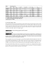
Unit
EVO-15R/SO
EVO-20R/SO
EVO-30R/SO
EVO-50R/SO
EVO-60R/SO
EVO-80R/SO
EVO-95R/SO
EVO-120R/SO
EVO-150R/SO
Содержание EVO-R
Страница 1: ...User s Manual EVO R COMPACT AIR HANDLING UNIT WITH ROTARY HEAT RECOVERY ...
Страница 18: ...18 4 1 Performance curve ...
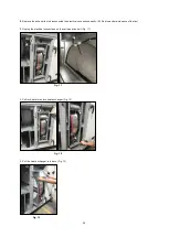
Страница 31: ...31 3 Plug the electrical connections on the damper actuator Fig 34 Fig 33 Fig 34 ...
Страница 33: ...33 CHAPTER 7 WIRING DIAGRAM OVERVIEW 7 1 EVO 15R Wiring Diagrams EVO 15R STANDART UNIT WIRING DIAGRAM Fig 37 ...
Страница 34: ...34 Fig 38 EVO 15R CONTROL PANEL DIAGRAM ...
Страница 35: ...35 EVO 15R ACCESSORIES DIAGRAM 1 Fig 39 ...
Страница 36: ...36 EVO 15R ACCESSORIES DIAGRAM 2 Fig 40 ...
Страница 37: ...37 7 2 EVO 20R Wiring Diagrams EVO 20R STANDART UNIT WIRING DIAGRAM Fig 41 ...
Страница 38: ...38 EVO 20R CONTROL PANEL DIAGRAM Fig 42 ...
Страница 39: ...39 EVO 20R ACCESSORIES DIAGRAM 1 Fig 43 ...
Страница 40: ...40 EVO 20R ACCESSORIES DIAGRAM 2 Fig 44 ...
Страница 41: ...41 7 3 EVO 30R Wiring Diagrams EVO 30R STANDART UNIT WIRING DIAGRAM Fig 45 ...
Страница 42: ...42 EVO 30R CONTROL PANEL DIAGRAM Fig 46 ...
Страница 43: ...43 EVO 30R ACCESSORIES DIAGRAM 1 Fig 47 ...
Страница 44: ...44 EVO 30R ACCESSORIES DIAGRAM 2 Fig 48 ...
Страница 45: ...45 7 4 EVO 50R Wiring Diagrams EVO 50R STANDART UNIT WIRING DIAGRAM Fig 49 ...
Страница 46: ...46 EVO 50R CONTROL PANEL DIAGRAM Fig 50 ...
Страница 47: ...47 EVO 50R ACCESSORIES DIAGRAM 1 Fig 51 ...
Страница 48: ...48 EVO 50R ACCESSORIES DIAGRAM 2 Fig 52 ...
Страница 49: ...49 7 5 EVO 60R Wiring Diagrams EVO 60R STANDART UNIT WIRING DIAGRAM Fig 53 ...
Страница 50: ...50 EVO 60R CONTROL PANEL DIAGRAM Fig 54 ...
Страница 51: ...51 EVO 60R ACCESSORIES DIAGRAM 1 Fig 55 ...
Страница 52: ...52 EVO 60R ACCESSORIES DIAGRAM 2 Fig 56 ...
Страница 53: ...53 7 6 EVO 80R Wiring Diagrams EVO 80R STANDART UNIT WIRING DIAGRAM Fig 57 ...
Страница 54: ...54 EVO 80R CONTROL PANEL DIAGRAM Fig 58 ...
Страница 55: ...55 EVO 80R ACCESSORIES DIAGRAM 1 Fig 59 ...
Страница 56: ...56 EVO 80R ACCESSORIES DIAGRAM 2 Fig 60 ...
Страница 57: ...57 7 7 EVO 95R Wiring Diagrams EVO 95R STANDART UNIT WIRING DIAGRAM Fig 61 ...
Страница 58: ...58 EVO 95R CONTROL PANEL DIAGRAM Fig 62 ...
Страница 59: ...59 EVO 95R ACCESSORIES DIAGRAM 1 Fig 63 ...
Страница 60: ...60 EVO 95R ACCESSORIES DIAGRAM 2 Fig 64 ...
Страница 61: ...61 7 8 EVO 120R Wiring Diagrams EVO 120R STANDART UNIT WIRING DIAGRAM Fig 65 ...
Страница 62: ...62 EVO 120R CONTROL PANEL DIAGRAM Fig 66 ...
Страница 63: ...63 EVO 120R ACCESSORIES DIAGRAM 1 Fig 67 ...
Страница 64: ...64 EVO 120R ACCESSORIES DIAGRAM 2 Fig 68 ...
Страница 65: ...65 7 9 EVO 150R Wiring Diagrams EVO 150R STANDART UNIT WIRING DIAGRAM Fig 69 ...
Страница 66: ...66 EVO 150R CONTROL PANEL DIAGRAM Fig 70 ...
Страница 67: ...67 EVO 150R ACCESSORIES DIAGRAM 1 Fig 71 ...
Страница 68: ...68 EVO 150R ACCESSORIES DIAGRAM 2 Fig 72 ...


