


Water/Methanol Injection V2
8
© 2020 AEM Performance Electronics
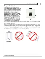
Note:
All tanks are tested for leaks during assembly. A special sealant adhesive is used to bond the plastic tank
to the metal fitting.
DO NOT
attempt to tighten the fitting any further!
The pump must be located in the same area as the tank and should be mounted at or below the lowest fluid
level height.
Take note of the direction of flow, indicated by the arrows on the pump body, when mounting the pump.
Use four #8 sheet metal screws along with the 4 small washers or the #8-32 bolts and nylock nuts to mount the
pump. The pump can be mounted in any position horizontally or vertically. Once the tank and pump are
mounted, cut the appropriate length of tubing needed to connect the outlet fitting on the tank to the inlet fitting
on the pump. Make sure there are no sharp bends in the tubing. Cut the tubing to length with a clean
perpendicular slice using a sharp razor blade, making sure the ends are clean and square. Push in the hose at
the tank and pump to install. Make sure they are pushed in all the way and check with a light tug on the hose.
Secure the hose to the chassis using sections of the supplied hose routing strip or with zip-ties.
Controller Install
The progressive controller is
NOT
waterproof
and should
NOT
be mounted in the engine bay!
Find a convenient
location for the controller inside the driver’s compartment. The adjustment knobs should remain in an accessible
location but still remain protected from possible water incursion. If you need to extend the wires to mount the
controller use at least 16 AWG wire for the pump and controller ground circuits and 18 AWG for the remainder.


