530-268
P2008 © Firma WJG, Braunschweig. Nachdruck oder Vervielfältigung nur mit ausdrücklicher Genehmigung
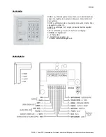
The Terminal Block:
1. DOOR BELL N.O.: 12 V DC connector for an external buzzer.
2. DOOR SENS: Connector for a magnetic door switch. It has the functions as follows: a) It is relocking of the
door immediately to avoid many entries at once. b) It sets off the alarm when somebody tries to open the door
by force. The alarm will last for 60 seconds and can be stopped by a user code 1. c) It sets off an alarm when
the door is open for a longer time then it is allowed by programming. The alarm can be stopped by closing the
door. d) If you have a system including multiple keypads all will be deactivated but the one which is in use. e) If
you do not use the connector DOOR SENS connect it to [15] (-) GND of the wire harness.
3. 12-24V AC/DC: This is the connector for the power supply of the keypad.
4. EG IN: Connector for an external door opener which is situated indoors usually. (NPN-open-collector-contact)
5 – 7: OUTPUT 1: These are relay dry contacts: 5) Contact N.C. (
normally closed). 6) COM provides the power
for OUTPUT 1. 7) Contact N.O. (
normally open).
The Wire Harness:
1 – 2. N.C. TAMPER: Sabotage contact for a 24h-alarm strip. This NC-contact sets off an alarm when somebody
tries to prize open the keypad.
3 – 7. DOOR LED, ALARM LED, AUXILIARY LED: Contacts for the LEDs DOOR (3-4), ALARM (5-6) and AUX (7).
8. KEYPAD ACTIVE OUTPUT OR ALARM OUTPUT: The function of this NPN-transistor is defined by the position
of the “K or A”-jumper. K) KEYPAD ACTIVE OUTPUT activates e.g. the light, a camera or a siren when the
keypad gets used. A) ALARM OUTPUT activates an external signal to a remote control station when an alarm
sets off (see above).
9 – 11. OUTPUT 2 RELAY: This is an auxiliary relay with COM, N.C. and N.O. contacts. It is ideal to connect the
keypad to an alarm system.
12. OUTPUT 3: This is an auxiliary NPN-transistor also for connecting to an alarm system.
13. OUTPUT 1 INHIBIT: This is a N.O. contact to connect an interlock circuit.
14. INTERLOCK CONTROL: This is a NPN-transistor which normally is inactive. If a valid user code is entered it is
blocking other keypads in the system to make sure that only one door can be opened at one time.
15. GND: Grounding.
16. DURESS OUTPUT: When a wrong code is entered 10 times
consecutively this contact will block the keypad
completely. The contact can be activated by entering a DURESS-Code as well. To unblock the keypad again you
need a user code 1.
Further Connections:
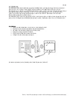
A: The Sabotage contact which gets adjourn if somebody try to break the keypad.
B: „K or A“-jumper. If set to „KEY“ KEYPAD ACTIVE OUTPUT is active otherwise ALARM OUTPUT with „AL“.
C: DAP-(Direct Access to Programming)-jumper to reset the code programming. In case you have forgotten the
master code implement following steps:
•
Disconnect the power supply of the keypad.
•
Open the keypad.
•
Switch the DAP-jumper to ON.
•
Reconnect the power supply of the keypad.
•
The built-in buzzer should give a continuous sound.
•
Now set the DAP-jumper to OFF again and the buzzer must stop.
•
Now the keypad is in the programming mode.
•
Arrange a new master code (for details see below).
•
Set up the all other codes with the help of the new master code.
Visual (LED MAIN) and acoustic (built-in buzzer) signals and their meanings:
MAIN permanent / buzzer off: keypad is in programming mode.
MAIN 1x / buzzer 1x: Every time you hit a key.
MAIN 2x / buzzer 2x: Entry of a correct code.
MAIN 5x / buzzer 5x: Entry of a false code.
MAIN flashes every 2 seconds / buzzer permanent: DAP-jumper is set to ON.
MAIN flashes every 2 seconds / buzzer off: keypad is in stand-by-mode


