


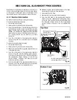


2-3-2
H9500MA
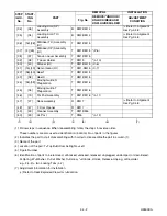
Adjust the X Value for maximum envelope.
(pg. 2-3-3) (Use Alignment Tape.)
Check to see that the tape is not creasing
and that there is no slack on the supply
and take-up side Guide Rollers.
(Use a blank tape.)
Adjust the height of the Guide Rollers
(Supply side and take-up side).
(Use a blank tape.) (pg. 2-3-3)
Loading (Use a blank tape.)
Adjust the envelope. (pg. 2-3-4)
Check the envelope.
Adjust the Audio Section.
(Azimuth Alignment) (pg. 2-3-4)
Check the audio output.
Check the following:
1. X Value (pg. 2-3-3)
2. Envelope (pg. 2-3-4)
Adjust the X value and envelope.
Not good
Do the final tape-traveling test to see that
the tape runs normally in play mode with-
out creasing or slacking.
Completion
Not good
OK
OK
OK
Not good
Not good
OK
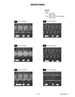
Flowchart of Alignment for tape traveling
1-A
1-A
1-B
1-C
1-C
1-D
1-D
1-B, 1-C
1-B, 1-C
1-A
1.Tape Interchangeability Alignment
Note:
To do these alignment procedures, make sure that the
Tracking Control Circuit is set to the center position
every time a tape is loaded or unloaded. (Refer to
page 2-3-4, procedure 1-C, step 2.)
Equipment required:
Dual Trace Oscilloscope
VHS Alignment Tape (FL6NS8)
Guide Roller Adj. Screwdriver
X-Value Adj. Screwdriver
Note: Before starting this Mechanical Alignment, do all
Electrical Adjustment procedures.
Содержание VCR-D 4501
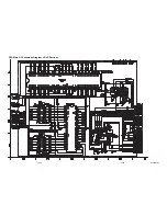
Страница 30: ...Main 1 9 Schematic Diagram VCR Section 1 10 3 1 10 4 H9504SCM1 ...
Страница 32: ...1 10 7 1 10 8 H9504SCM3 Main 3 9 Schematic Diagram VCR Section ...
Страница 33: ...Main 4 9 Schematic Diagram VCR Section 1 10 9 1 10 10 H9504SCM4 ...
Страница 34: ...Main 5 9 Schematic Diagram VCR Section 1 10 11 1 10 12 H9504SCM5 ...
Страница 35: ...Main 6 9 Schematic Diagram VCR Section 1 10 13 1 10 14 H9504SCM6 ...
Страница 36: ...Main 7 9 Schematic Diagram VCR Section 1 10 15 1 10 16 H9504SCM7 ...
Страница 37: ...Main 8 9 DVD Open Close Schematic Diagram VCR Section 1 10 17 1 10 18 H9504SCM8 ...
Страница 38: ...1 10 19 1 10 20 Main 9 9 Schematic Diagram VCR Section H9504SCM9 ...
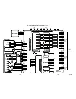
Страница 40: ...1 10 23 1 10 24 Jack Schematic Diagram VCR Section H9504SCJ ...
Страница 41: ...1 10 25 1 10 26 Function Schematic Diagram VCR Section H9504SCF ...
Страница 42: ...1 10 27 1 10 28 AFV Schematic Diagram VCR Section H9504SCAFV ...
Страница 44: ...1 10 31 Main CBA Bottom View BH9510F01014A 1 10 32 ...
Страница 48: ...DVD Main 1 3 Schematic Diagram DVD Section H9504SCD1 1 10 39 1 10 40 ...
Страница 49: ...1 10 41 1 10 42 DVD Main 2 3 Schematic Diagram DVD Section H9504SCD2 ...
Страница 51: ...DVD Main 3 3 Schematic Diagram DVD Section 1 10 45 1 10 46 H9504SCD3 ...
Страница 98: ...VCR D 4501 H9504ED 2004 04 01 ...