


MA
TER
IA
L
M
ED
I
U
M
1
/4
" 3
/
8" 1
/2
"
SO
F
T
E-F D-E A-B
D-E C-D
A
HA
RD
C-D B-C
A
V
ER
Y
HA
RD
D-E C-D C-D
C
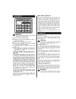
UTTER S
I
ZE
SPEED SELE
C
T
I
O
N
CHA
RT
Loosen lock knob and raise stop bar.
Rotate depth stop until the highest depth stop is
aligned with the stop bar.
Raise cutter by unlocking plunge lock lever.
Place router on flat surface, and lower router until tip
of cutter barely touches flat surface.
Lock plunge lock lever to position cutter at "zero"
depth of cut.
Lower stop bar against depth stop, then tighten lock
knob securely. The highest stop now becomes the
"zero" depth of cut setting.
VA
R
IAB
LE SPEED
C
O
N
TROL SELE
C
TOR
Your router has a variable speed control selector (2) designed
to allow operator control of speed and torque limits. You
can make speed selections best suited to the type of cut,
the material being cut, and the size of bit being used. The
variable speed control selector allows you to adjust
router speed from 1
50
00 to
300
00 min
-1
. There is a six-
step scale (A to F) on the variable speed control selector.
To increase the speed and torque of your router, turn the
variable speed control selector to a higher setting (F).
Turn to a lower setting to decrease speed and torque.
N
OTE
:
If you do not want to use the variable speed
control selector, turn it to the highest possible setting,
and the feature will not be active.
The speed selection chart shown gives suggested speed
settings based on the diameter of the cutter and the type
of material being routed.
We suggest that you practice with the variable speed
feature of your router before installing a cutter and
making cuts in wood.
WA
R
NING:
Failure to unplug your router could result in acciden-
tal starting causing serious injury.
(FIG.
10
)
ZERO RESET
IN
D
ICA
TOR
The zero reset indicator allows you to use the scale
provided on the housing to make quick depth of cut
changes to existing depth of cut settings. Simply choose
a reference point on the scale and slide the zero reset
indicator up or down the scale the distance required for
new depth of cut. Then change stop bar position by
loosening lock knob and adjusting stop bar until red line
on zero reset indicator moves back to reference point.
Tighten lock knob securely to lock stop bar in new
position. The cutter position will now increase or decrease
the exact distance the stop bar was adjusted.
N
OTE
:
Each mark on the inch scale indicates 1/16 in.
(1.6 mm).
S
WI
T
CH
(FIG.
11
)
We suggest that you practice with your router before
installing a cutter and making cuts in wood.
ROUT
ING
(FIG.
1
2)
For ease of operation and maintaining proper control,
your router has two handles (3), one on each side of the
router base. When using your router hold it firmly with
both hands.
Before starting the router, unplug it and make sure the
cutter is securely tightened in collet nut and that depth of
cut is properly set.
Plug router into power supply, turn it on, and let motor
build to its full speed, then gradually plunge or feed cutter
into workpiece.
D
o
not
let the cutter contact workpiece
before turning on router and allowing it to develop full
speed.
Remain alert and watch what you are doing.
D
o
not
operate router when fatigued or under the influence of
drugs, alcohol, or any medication.
ROUT
ING
G
ROO
V
ES
(FIG.
13
)
When routing across the face of boards, set router at
desired depth of cut, place the edge of router base
against workpiece, and turn on the router. Slowly feed
the cutter into the workpiece along desired line of cut.
To turn the router
O
N
, press the lock-off button (4) and
squeeze the switch (15).
O
FF
, release both the switch &
lock-off button.
CA
UT
I
O
N:
WA
R
NING:
If desired depth of cut is greater than can be safely
cut in one pass, make cuts in two or more passes.
OPER
A
T
I
O
N
6
mm
8
mm
1
2mm
- 1
1
-
A
DJUST
M
E
N
TS
Содержание RT 1350 E
Страница 1: ...Instructions for use RT 1350 E ...
Страница 3: ... 3 TO SPEED TO SPEED Fig 7 Fig 8 Fig 9 Fig 10 Fig 12 9 10 8 10 9 12 11 2 1 Fig 11 ...
Страница 4: ... 4 Fig 13 Fig 14 Fig 15 Fig 16 Fig 18 Fig 19 20 16 28 16 29 34 34 35 35 Fig 17 30 31 32 33 32 33 ...
Страница 5: ... 5 Fig 20 Fig 21 Fig 22 T L Fig 23 36 ...
Страница 14: ......
Страница 15: ......
Страница 16: ...w w w a e g p t c o m AEG Elektrowerkzeuge Max Eyth Straße 10 D 71364 Winnenden Germany ...


