


15
Installation - for contractors
10.
Appliance installation
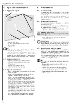
10.1
Wall mounting
!
Material losses
Only mount the natural stone heater on a flat wall, as
otherwise cracks may develop in the natural stone
panel due to stresses.
In the event of unevenness
in the mounting wall, level the surface before tigh
-
tening the fixing screws.
!
Material losses
Do not tilt or tip the natural stone heater.
Otherwise,
it may break.
!
Material losses
If the fixing screws are over-tightened, the rawl plugs
in the natural stone panel may over-rotate and be
-
come loose.
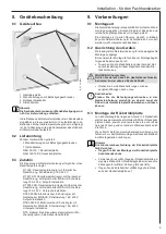
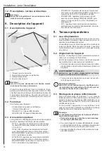
» Measure dimensions a and b for the drill holes on the
natural stone heater.
» Based on the measurements, drill the holes in a wall
with sufficient load-bearing capacity.
Maintain a saf-
ety margin of 100 mm on all sides (e.g. dimension b
+ 100 mm).
» Screw the hexagon screws far enough into the drill
holes that the natural stone heater can still be hoo-
ked over the screw heads with the open slots in the
wall mounting brackets.
» Hang the natural stone heater. Tighten the hexagon
screws. Relieve any stress by slightly loosening the
fixing screws in the natural stone panel.
Then retigh-
ten the fixing screws.
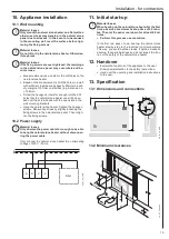
10.2 Power supply
!
Material losses
Only shorten the power cable far enough to be able
to hang the natural stone heater without disconnec
-
ting the power cable.
Only connect the natural stone heater to an alternating
voltage of 230 V / 50 Hz.
N
N
L’
L
NSH
L
N
PE
26
_0
7_
30
_00
10
11.
Initial start-up
!
Material losses
When heating up the natural stone heater for the first
time, observe a maximum heat-up time of 20 minu
-
tes.
Then let the panel cool down for at least 60 mi
-
nutes.
»
Perform this process one more time.
In the first two days of use, heat up the natural stone
heater step-by-step to the required room temperature.
This way, you avoid hairline cracks. If hairline cracks do
develop, these are harmless and do not impair the func-
tion or the safety of the natural stone heater.
12.
Handover
» Explain the functions of the appliance to the user.
Draw special attention to the safety instructions.
» Hand over the operating and installation instructions
to the user.
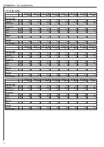
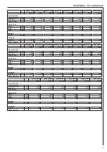
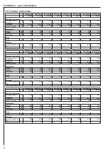
13.
Specification
13.1
Dimensions and connections
B
H
230 V
H
23
H
23
70
b
35
40
a
26
_0
7_
30
_00
13
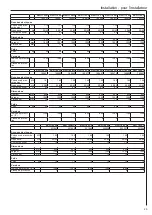
13.2
Minimum clearances
100
mm
50
0 m
m
100
mm
100
mm
100
mm
100
mm
300
mm
100
mm
26
_0
7_
30
_000
3
Содержание 189648
Страница 35: ...35 Notities ...


