background image

Information subject to change

96-8005353_02-17-2022

8504 OPERATOR’S MANUAL – SECTION 6

24

Connect Your Output Cables

1. 

Make sure both amplifiers are disconnected 

from AC power.

2. 

Remove the 3/8-inch nuts from the Output and 
GND terminals on the Master amplifier and 
from the Output terminal on the Follower ampli

-

fier.

3. 

Connect the end of the black output cable 
terminated with a 3/8-inch ring terminal to the 
Master amplifier’s back-panel GND connector.

4. 

Connect one leg of the red output cable (ter

-

minated with a 3/8-inch ring terminal) to the 
Master amplifier’s back-panel Output connec

-

tor. Connect the other leg to the Follower am

-

plifier’s back-panel Output connector. 

DO NOT 

CONNECT TO A LOAD AT THIS TIME.

5. 

Replace the 3/8-inch nuts on all output termi

-

nals. 

IMPORTANT: Torque the nuts to 10 

lbs./foot.  

6. 

Replace the output terminal covers on both 
amplifiers and secure.

Amplifier Current Check

1.  Connect an oscilloscope or other measur

-

ing device to the back panel BNC connectors 
labeled IMON on both the Master and the Fol

-

lower amplifiers.

2.  Turn down the level of your signal source.
3.  Make sure both amplifier’s back panel breaker 

switches are in the ON position, and then press 
the Standby-Run switch on each of the ampli

-

fier’s front panels to energize the amplifiers. 

4.  Wait for the green RUN LED to illuminate on 

the amplifier.

5.  Adjust your signal source to input a 1-kHz sine 

wave of 100 mV into the amplifier.

6.   Measure the current being produced at the out

-

put of the IMON on each amplifier (1V = 20A). 
Be sure to measure AC voltage at the IMON 
port as an RMS value. Apart from switching 
current, no significant current should be ob

-

served. Current output should be less than 2A 
(0.1V on the IMON output).

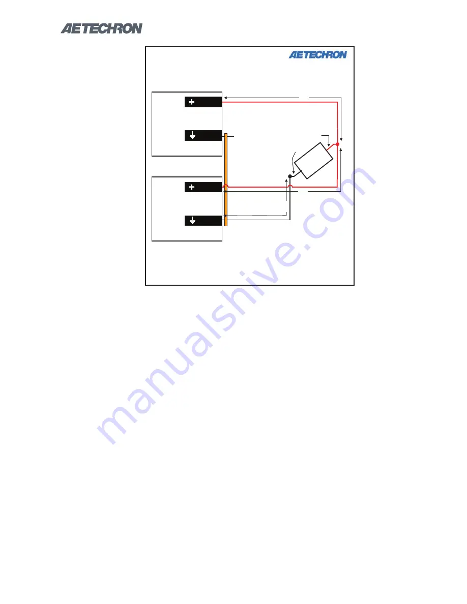
Figure 6.10 – Critical output wire lengths for 8504 parallel systems

TWO 8504 AMPLIFIERS PARALLELED


(CRITICAL WIRE LENGTHS)

OUTPUT

LOAD

OUTPUT

AMP #1

MASTER

AMP #2

FOLLOWER

C

D

OUTPUT

GND

OUTPUT

GND

A

Ÿ

Both wires of length “A” should be of the same length ±1/4 inch.

Ÿ

Wire lengths “A” and “B” may or may not be of the same length. 

Ÿ

The length of wire “C” is not critical.

Ÿ

The length of wire “D” is not critical.

Ÿ

For maximum current output, all wire lengths should be as short as is practical.

A

B

Содержание 8504

Страница 1: ...8504 Operator s Manual Wide Bandwidth High Power Digital Amplifier 574 295 9495 www aetechron com 2507 Warren Street Elkhart IN 46516 ...

Страница 2: ...nt up to 16A per phase EN 61000 4 6 Electromagnetic compatibility EMC Part 4 Testing and measurement techniques voltage dips short interruptions and voltage variations immunity tests for equipment with input current up to 16A per phase EN 61000 4 5 Electromagnetic compatibility EMC Part 4 Testing and measurement techniques voltage dips short interruptions and voltage variations immunity tests for ...

Страница 3: ... of our authorized service centers of your need for warranty service you will receive an authorization to return the product for service All components must be shipped in a factory pack or equivalent which if needed may be obtained from us for a nominal charge We will take corrective actions and return the product to you within three weeks of the date of receipt of the defective prod uct or will m...

Страница 4: ...rols Connectors 12 5 Advanced Configuration 13 5 1 DIP Switch Configurations 14 5 2 Custom Compensation 16 6 Applications 17 6 1 Emergency Standby Switch or Safety Interlock 17 6 2 Controlled Voltage vs Controlled Current Modes of Operation 17 6 3 Driving Reactive Loads 20 6 4 8504 Multi amp Systems 20 7 Maintenance 29 7 1 Clean Amplifier Filter and Grills 29 8 Troubleshooting 30 8 1 Introduction ...

Страница 5: ...ng reac tive loads As frequencies increase the effective impedance of the load becomes a much larger part of the total load to be driven especially with inductive loads like coils However when driving reactive loads the 8504 is capable of receiving reprocessing and returning to the load up to 5X its rated power The result is a bench top system capable of 20 kVA output while drawing less than 4 kW ...

Страница 6: ...he back of the amplifier for heated air to escape The amplifier should be mounted in a rack that is adequately ventilated and not sealed Likewise the front of the amplifier should be unobstructed to allow cool air to enter the amplifier WARNING alerts you to hazards that could result in severe injury or death Note the explanation of the hazard and the instructions for avoiding it WARNING CAUTION i...

Страница 7: ...SHOCK HAZARD Output potentials can be lethal Output cover must remain installed at all times to protect against HAZARDOUS LIVE VOLTAGES WARNING Figure 3 2 Connecting the Load Figure 3 3 Output Safety Cover 3 1 2 Output Connections Connection to the output of the amplifier is to a pair of high current output terminals Wires ter minated with 3 8 inch ring terminals are recom mended when connecting t...

Страница 8: ... be used to en able disable the unbalanced input connector and DIP switch 2 can be used to enable disable the balanced input connector When these two DIP switches are placed in the UP position factory default the input connectors are enabled When the DIP switches are placed in the DOWN position the input connectors are disabled See Figure 3 5 for DIP switch locations The risk of lethal ELECTRICAL ...

Страница 9: ... AC supply to the three terminal bar rier strip located on the amplifier back panel see Figure 3 6 and 3 7 Install AC inlet cover prior to connecting to the sup ply source See Figure 3 8 Start up Procedure 1 Turn down the level of your signal source 2 Place the back panel breaker switch in the ON position 3 Press the front panel Standby Run switch to the Run position to energize the ampli fier 4 W...

Страница 10: ... transform ers are not Figure 4 1 Front Panel Controls and Indicators To release the amplifier from Standby mode 1 High Low Line error Clear the over or un der voltage condition The amplifier will resume operation when the input voltage is brought within the operating range of the amplifier 2 Overtemp condition Remove the input signal from the amplifier and leave the amplifier with the Standby Run...

Страница 11: ...ors the temperature inside the high voltage transformers and in the output stage heat sinks The amber Overtemp indicator will light and the amplifier will be placed in Standby mode Figure 4 2 Back Panel Controls and Connectors when the temperature sensors detect a condition that would damage the amplifier If the Overtemp pulse is extremely short as in the case of defec tive wiring or switches this...

Страница 12: ...e Monitor Connector This unbalanced BNC port allows for connection to voltage monitor ing equipment The voltage monitor output is 1V 40V Multi amp Connectors These two 9 pin D sub connectors labeled Interconnect A and Intercon nect B can be used to connect two 8504 ampli fiers in a Parallel or Push Pull configuration They can also be used to set up a Safety Interlock circuit to automatically place...

Страница 13: ... Enable electronic gain matching to optimize parallel operation of two 8504 amplifiers Select and enable a synthetic impedance from 0 125 ohms to 0 875 ohms 8504 Default DIP Switch Settings Red Default DIP SWITCH SETTINGS UP DOWN 1 UNBALANCED INPUT ON OFF 2 BALANCED INPUT ON OFF 3 DC SERVO ON OFF 4 OPERATION MODE CV CC 5 COMPENSATION NETWORK 2 ON OFF 6 COMPENSATION NETWORK 1 ON OFF 7 CONTROL CONFI...

Страница 14: ...s for selecting the best compensation option for your application see the topic Controlled Current Operation in the Applications section of this manual If neither of the available RC networks is suitable for your application please contact AE Techron Technical Support SW 5 Compensation Network 2 When the 8504 amplifier is used in Controlled Current mode the current control loop is tuned with an RC...

Страница 15: ... including instructions for selecting the best compensation option for your application see the topic Controlled Current Operation in the Applica tions section of this manual If neither of the avail able RC networks is suitable for your application please contact AE Techron Technical Support SW 7 Control Configuration When this switch is in the UP position default the amplifier will function as a ...

Страница 16: ... is disabled The synthetic impedance can be added in incre ments of 0 125 ohms by setting one or more of the synthetic impedance switches in the UP position Refer to Figure 5 2 for all available synthetic im pedance switch settings SW 21 24 Current Limit These four switches control the current limit set tings for the amplifier When all four switches are Figure 5 3 Current Limit Switch Configuratio...

Страница 17: ...tion AE Techron 8504 amplifiers can be field configured to operate as Voltage Amplifiers Voltage Con trolled Voltage Source or as Transconductance Amplifiers Voltage Controlled Current Source The mode selection is made via the back panel DIP switch 4 See the Advanced Configuration section for more information When configured as a Controlled Voltage source voltage amplifier the amplifier will provi...

Страница 18: ...fectively We recommend that you power up and enable the amplifier in Controlled Voltage mode without at taching a load before configuring your amplifier for Controlled Current operation This will allow you to verify that the input signal and the amplifier are operating correctly Once this initial check is completed power down the amplifier attach your load and move the back panel Operation Mode DI...

Страница 19: ...ork 2 for your application See Figure 6 4 These compensation networks NOTE Load Resistance R is assumed to be 5 ohms STEP 3 Enable Compensation Network are enabled when Compensation Network 1 DIP switch SW 6 or Compensatlon Network 2 DIP switch SW 5 on the Master amplifier module is set to the ON UP position If your load inductance falls outside of these ranges or if your load resistance is greate...

Страница 20: ...p to five times the rated power of the amplifier when driving reactive loads 6 4 8504 Multi amp Systems The 8504 amplifier may be used with one other 8504 amplifier in either a Parallel or a Push Pull Series configuration The Parallel configuration will approximately double the continuous current output to 120 Arms while the Push Pull configura tion will approximately double the voltage avail able...

Страница 21: ...Principles Following these basic principles will help to ensure the safety of your equipment and personnel One Master Amplifier Multi amp configurations require one amplifier configured as a Master amplifier and the second amplifier in the system configured as a Follower amplifier Use Only 8504 Amplifiers Use only AE Techron 8504 amplifers to construct a 8504 multiamp system Do not combine differe...

Страница 22: ...rmed using an oscillo scope or a floating digital multimeter with a resolu tion of at least three digits Both testing methods are provided below Testing Using an Oscilloscope 1 Connect from a signal generator to the BNC or WECO signal input connector on the back panel of the Master amplifier Note that if the WECO connector is used for signal input DIP switch 1 on the Master amplifier should be pla...

Страница 23: ...or and the GND bus bar 6 Adjust your signal source to input a 1 kHz 2 5 Vrms sinewave into the Master amplifier input The measured output should be at or very near to 100 Vrms Record the measured output 7 Connect the digital multimeter between the Follower amplifier s Output connector and the GND bus bar The measured output should be at or very near to 100 Vrms Record the mea sured output 8 Set yo...

Страница 24: ...N on both the Master and the Fol lower amplifiers 2 Turn down the level of your signal source 3 Make sure both amplifier s back panel breaker switches are in the ON position and then press the Standby Run switch on each of the ampli fier s front panels to energize the amplifiers 4 Wait for the green RUN LED to illuminate on the amplifier 5 Adjust your signal source to input a 1 kHz sine wave of 10...

Страница 25: ...fier continue with the system setup IMPORTANT If current exceeds 2A 0 1V from either amplifier DO NOT complete the system setup Contact AE Techron Techni cal Support for assistance 8 Slowly raise the input voltage from 100 mV to to 2 5V while continuing to monitor current at IMON IMPORTANT If current exceeds 2A 0 1V from either amplifier at any time DO NOT complete the system setup Contact AE Tech...

Страница 26: ...in the UP ON position 3 Build your output cables A Build two cables for output wiring The wires should be terminated at one end into a spade lug ring terminal or other terminal suitable for the system output and adaptable to the connectors on the load Terminate the other end of each cable with 3 8 inch ring terminal ends to facilitate con nection to each amplifier s output connec tors B Build a Br...

Страница 27: ... system so the Follower amplifier is said to be interlocked with the Master amplifier The func tions controlled by the Master amplifer include input signal operating status mode of operation controlled voltage or controlled current operation and amplifier compensation Because the amplifiers in a multiamp system are interlocked the main and fault status indicators of both amplifiers in the system m...

Страница 28: ...plifiers is turned on Next check the voltage level of the AC supply Once the fault condition has been cleared both amplifiers will return automatically to Run mode If the High Low Line indicator does not turn off or if the system does not return from Standby one or both amplifiers may require servicing See the Troubleshooting section in this manual for more information Overtemp Both amplifiers mon...

Страница 29: ...e the filter located behind the front grill 4 Using a vacuum cleaner vacuum the front ven tilation grill the grill filter and the back ventila tion exit grill 5 Using a damp cloth clean the amplifier front panel and the rear ventilation grills Also use the damp cloth to clean the front grill and filter If necessary these can be immersed in warm soapy water 6 Dry the front panel filter and grills w...

Страница 30: ...the AC supply into the amplifier is higher or lower than the operable range First check to make sure the amplifier s back panel breaker is turned on Next check the voltage level of the AC supply If the AC mains voltage is more than 10 outside the range of the operating voltage increase or reduce the AC mains voltage to the proper level When the line voltage condition is corrected the amplifier wil...

Страница 31: ... is Illuminated The 8504 contains protection circuitry that disables the amplifier if an output stage is behaving abnor mally This usually indicates an output transistor has shorted To clear the Fault condition follow these steps 1 Turn off the signal source 2 Turn off the AC mains 3 Turn AC mains power back on If the Fault LED doesn t illuminate again press the Standby Run switch to place the amp...

Страница 32: ...F ON OFF ON ON 36 72 ON ON ON OFF ON OFF ON 36 56 ON ON ON OFF ON OFF OFF ON 36 41 ON ON ON OFF ON OFF OFF OFF 36 25 ON ON ON OFF OFF ON ON ON 36 10 ON ON ON OFF OFF ON ON 35 94 ON ON ON OFF OFF ON ON 35 79 ON ON ON OFF OFF ON 35 63 ON ON ON OFF OFF OFF ON ON 35 47 ON ON ON OFF OFF OFF ON 35 31 ON ON ON OFF OFF OFF OFF ON 35 16 ON ON ON OFF OFF OFF OFF OFF 35 00 ON ON OFF ON ON ON ON ON 34 85 ON O...

Страница 33: ...FF OFF OFF OFF ON 30 31 ON ON OFF OFF OFF OFF OFF ON 30 16 ON ON OFF OFF OFF OFF OFF OFF 30 00 ON OFF ON ON ON ON ON ON 29 85 ON OFF ON ON ON ON ON OFF 29 69 ON OFF ON ON ON ON OFF ON 29 54 ON OFF ON ON ON ON OFF OFF 29 38 ON OFF ON ON ON OFF ON ON 29 22 ON OFF ON ON ON OFF ON OFF 29 06 ON OFF ON ON ON OFF OFF ON 28 91 ON OFF ON ON ON OFF OFF OFF 28 75 ON OFF ON ON OFF ON ON ON 28 60 ON OFF ON ON ...

Страница 34: ... OFF OFF ON OFF 22 81 ON OFF OFF ON OFF OFF OFF ON 22 66 ON OFF OFF ON OFF OFF OFF OFF 22 50 ON OFF OFF OFF ON ON ON ON 22 35 ON OFF OFF OFF ON ON ON 22 19 ON OFF OFF OFF ON ON ON 22 04 ON OFF OFF OFF ON ON 21 88 ON OFF OFF OFF ON OFF ON ON 21 72 ON OFF OFF OFF ON OFF ON 21 56 ON OFF OFF OFF ON OFF OFF ON 21 41 ON OFF OFF OFF ON OFF OFF OFF 21 25 ON OFF OFF OFF OFF ON ON ON 21 10 ON OFF OFF OFF OF...

Страница 35: ... ON ON OFF OFF OFF OFF OFF 15 00 OFF ON OFF ON ON ON ON ON 14 85 OFF ON OFF ON ON ON ON OFF 14 69 OFF ON OFF ON ON ON OFF ON 14 54 OFF ON OFF ON ON ON OFF OFF 14 38 OFF ON OFF ON ON OFF ON ON 14 22 OFF ON OFF ON ON OFF ON OFF 14 06 OFF ON OFF ON ON OFF OFF ON 13 91 OFF ON OFF ON ON OFF OFF OFF 13 75 OFF ON OFF ON OFF ON ON ON 13 60 OFF ON OFF ON OFF ON ON OFF 13 44 OFF ON OFF ON OFF ON OFF ON 13 2...

Страница 36: ...OFF OFF ON OFF ON ON ON ON 7 35 OFF OFF ON OFF ON ON ON OFF 7 19 OFF OFF ON OFF ON ON OFF ON 7 04 OFF OFF ON OFF ON ON OFF OFF 6 88 OFF OFF ON OFF ON OFF ON ON 6 72 OFF OFF ON OFF ON OFF ON OFF 6 56 OFF OFF ON OFF ON OFF OFF ON 6 41 OFF OFF ON OFF ON OFF OFF OFF 6 25 OFF OFF ON OFF OFF ON ON ON 6 10 OFF OFF ON OFF OFF ON ON OFF 5 94 OFF OFF ON OFF OFF ON OFF ON 5 79 OFF OFF ON OFF OFF ON OFF OFF 5...

Страница 37: ...N ON OFF 2 19 OFF OFF OFF OFF ON ON OFF ON 2 04 OFF OFF OFF OFF ON ON OFF OFF 1 88 OFF OFF OFF OFF ON OFF ON ON 1 72 OFF OFF OFF OFF ON OFF ON OFF 1 56 OFF OFF OFF OFF ON OFF OFF ON 1 41 OFF OFF OFF OFF ON OFF OFF OFF 1 25 OFF OFF OFF OFF OFF ON ON ON 1 10 OFF OFF OFF OFF OFF ON ON OFF 0 94 OFF OFF OFF OFF OFF ON OFF ON 0 79 OFF OFF OFF OFF OFF ON OFF OFF 0 63 OFF OFF OFF OFF OFF OFF ON ON 0 47 OF...

Отзывы: