background image


AE TECHRON MULTI-AMP CONFIGURATION GUIDE 

97-8002465_09-19-14 

Information subject to change 

13


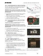
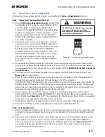
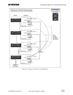
Figure 3.12 – Terminating the Amplifier Input 

3.9


Two or Three in Series – Single Ended 

Complete the following procedures to connect your amplifiers for 

Series – Single-Ended

 operation. 

3.9.1


Connect and Test Amplifier Interlock  


Using a 

DB-9 high-voltage interlock cable,

 connect from 

1.

the MASTER OUTPUT connector on the SIM-BNC-OPTOC 
card of the Master amplifier to the SLAVE INPUT 
connector on the SIM-BNC-OPTOC card of the first Slave 
amplifier. If configuring for a three amp system, use an 
additional DB-9 cable to connect from the MASTER 
OUTPUT of the first Slave amplifier to SLAVE INPUT on a 
second Slave amplifier. 


Using wiring appropriate for your application, load and 

2.

expected output, connect from the MASTER amplifier’s 
back-panel output connector labeled OUTPUT to the first 
SLAVE amplifier’s COM (2105/7224) or SAMPLED 
COMMON (2110/2120/7548/7796) connector. For an 
additional SLAVE amplifier in the system, connect from 
the first SLAVE amplifier’s OUTPUT connector to the 
second SLAVE amplifier’s COM or SAMPLED COMMON 
connector.  


On the MASTER amplifier, connect the output wiring to the back-panel output connector labeled COM 

3.

(2105/7224) or SAMPLED COMMON (2110/2120/7548/7796). On the last SLAVE amplifier, connect 
the output wiring to the back-panel output connector labeled OUTPUT. 

IMPORTANT: DO NOT connect the 

load at this time.


Terminate the input of the Master amplifier using a resistor-terminated barrier block connector (see 

4.

Figure 3.12

) or similar device. 


Power up each amplifier by switching to ON the front-panel ON/OFF switch (2105/7224 amplifiers) or 

5.

moving the back-panel AC Mains Switch/Circuit Breaker to the ON (up) position 
(2110/2120/7548/7796 amplifiers). Allow the amplifiers to come to the Ready state. When Ready, the 
amplifier Ready and Run LEDs will be lit. Note: Some amplifiers that have been custom-configured may 
require that you press the Enable button to bring the amplifier to the Ready state. Let the amplifiers run 
for several minutes in Ready state to allow DC offsets to stabilize. 


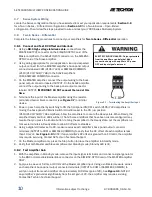
Using a digital voltmeter set to DC, measure across each amplifier’s back-panel output connector 

6.

terminals (OUTPUT to COM or SAMPLED COMMON) to verify that the DC offset of each amplifier is less 
than 10 mVdc. See 

Figure 3.13.

 NOTE: If any amplifier’s DC offset is greater than 10 mVdc, the amplifier 

may require servicing. Contact AE Techron Technical Support. 


On the Master amplifier only, press the Stop button to place the amplifier in Standby mode. 

7.


Verify that both Master and Slave amplifier enter Standby mode (Standby LED is lit). 

8.

3.9.2


Test Amplifier Gain 


With the amplifiers in Standby mode, remove the input signal termination and connect a signal generator 

1.

to the BNC or Removable Barrier Block connector on the SIM-BNC-OPTOC card of the MASTER amplifier 
ONLY. 


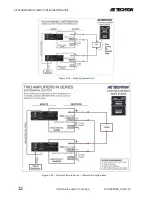
Apply a sine wave of 5Vrms at 100 Hz at the Master amplifier input. Using a voltmeter measure across 

2.

each amplifier’s back-panel output connector terminals (OUTPUT to COM or SAMPLED COMMON) to 
verify an output from each amplifier of approximately 100Vrms (gain of 20). See 

Figure 3.14.

 NOTE: If 

any amplifier’s gain varies significantly from the set gain of 20, the amplifier may require servicing. 
Contact AE Techron Technical Support. 

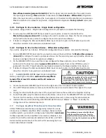
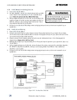
ELECTRIC SHOCK HAZARD. Output potentials 
from the amplifiers can be lethal. Make 
connections only with 

amplifiers’ AC power 

OFF and input signals removed.


Содержание 2100 series

Страница 1: ...Multi Amp Configuration Guide Step by Step Guide to Multi Amp Systems using AE Techron 2100 and 7000 Series Amplifiers 574 295 9495 www AETechron com 2507 Warren Street Elkhart IN 46516 ...

Страница 2: ...fiers 8 3 4 Configure Amplifiers Main Boards for Slave Operation 8 3 5 Remove Output Terminal Resistor 9 3 6 Attach Master Slave Labels optional 9 3 7 Series System Wiring 10 3 8 Two in Series Differential 10 3 9 Two or Three in Series Single Ended 13 4 Parallel Systems Configuration Wiring and Balancing 17 4 1 Install Ballast Resistors 17 4 2 Main Board Access 18 4 3 Disable Gain Controls 7224 am...

Страница 3: ...last Resistor Connected to Output Terminal 17 Figure 4 4 7796 Ballast Resistors Connected to Output Terminal 17 Figure 4 5 Access Panel Screw Locations 18 Figure 4 6 Gain Control Connection on Main Board 18 Figure 4 7 Gain Control Pin Settings 19 Figure 4 8 Connecting for Balancing Four in Parallel shown 19 Figure 4 9 Terminating the Amplifier Input 20 Figure 4 10 Main Board Balancing Control Loca...

Страница 4: ...ech Support for assistance with configuring a multi amp system for Controlled Current operation For assistance in determining the best multi amp configuration to meet your requirements please contact AE Techron This Guide will provide step by step instructions for setting up a Series or Parallel controlled voltage multi amp system using AE Techron 2100 or 7000 Series amplifiers 1 3 Multi Amp Confi...

Страница 5: ...lel inputs through the BNC input connectors and the terminated Removable Barrier Block connectors used to terminate the amplifier inputs during system setup Parallel wiring kits are recommended for all Parallel configurations 1 4 Accessory Recommendations by System Type Series Systems 2105 or 7224 Two in Series 2 SIM BNC OPTOC input cards 1 DB9M OPTOC cable 2105 or 7224 Three in Series 3 SIM BNC O...

Страница 6: ...rs Depending on the configuration to be used the OUTPUT terminal of one amplifier should only be directly connected to the next amplifier s COM or SAMPLED COMMON terminal to the load or to a ballast resistor 2 5 When Constructing Output Wiring Use These Basic Criteria In multi amplifier systems the quality gauge length and rating of the output wiring leading to the load can affect system performan...

Страница 7: ...that functions to synchronize the operation of all amps in the system and provides for optical isolation The input card allows you to designate via jumpers located on the card that the input card will function as a Master sending synchronization information or will function as a Slave receiving synchronization information Other options for system configuration and operation can also be selected vi...

Страница 8: ...M BNC OPTOC input card that is now configured for Slave operation move the shunts 2 positioned on the lower two pins of jumpers J12 and J13 and place them on the UPPER two pins of jumpers J12 and J13 This will allow the input signal received by the Slave amplifier to be inverted If desired configure the Removable Barrier Block input connector option on the Master input card to 3 allow the connecto...

Страница 9: ...fier is turned off for at least 3 5 minutes and the AC mains are disconnected Turn the power to the amplifier OFF 1 Remove the four hex head screws located along the left and 2 right edges of the amplifier front panel Remove the front cover by pulling straight towards you 3 3 4 3 Set Master Slave Jumpers On the main board locate the jumpers P1 and P2 1 Master Slave For Slave operation set both jum...

Страница 10: ...ving the back panel AC Mains Switch Circuit Breaker to the ON up position 2110 2120 7548 7796 amplifiers Allow the amplifiers to come to the Ready state When Ready the amplifier Ready and Run LEDs will be lit Note Some amplifiers that have been custom configured may require that you press the Enable button to bring the amplifier to the Ready state Let the amplifiers run for several minutes in Read...

Страница 11: ... the MASTER and SLAVE OUTPUT connectors to your load 2 Power up both amplifiers and allow them to come to the Ready state 3 Apply a sine wave of 5 Vrms at 100 Hz at the Master amplifier input Using a voltmeter measure across 4 the system load to verify an output from the system of approximately 200 Vrms See Figure 3 10 Check the completed system diagram in Figure 3 11 to verify proper system setup...

Страница 12: ...AE TECHRON MULTI AMP CONFIGURATION GUIDE 12 Information subject to change 97 8002465_09 19 14 Figure 3 10 Verifying System Gain Figure 3 11 Two Amplifiers in Series Differential Configuration ...

Страница 13: ... switch 2105 7224 amplifiers or 5 moving the back panel AC Mains Switch Circuit Breaker to the ON up position 2110 2120 7548 7796 amplifiers Allow the amplifiers to come to the Ready state When Ready the amplifier Ready and Run LEDs will be lit Note Some amplifiers that have been custom configured may require that you press the Enable button to bring the amplifier to the Ready state Let the amplif...

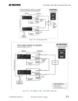
Страница 14: ... COMMON connector 2 and last SLAVE amplifier s OUTPUT connector to your load Power up all amplifiers and allow them to come to the Ready state 3 Apply a sine wave of 5Vrms at 100 Hz at the Master amplifier input Using a voltmeter measure across 4 the system load to verify an output from the system of approximately 200Vrms See Figure 3 15 Check the completed system diagrams in Figure 3 16 or 3 17 t...

Страница 15: ...AE TECHRON MULTI AMP CONFIGURATION GUIDE 97 8002465_09 19 14 Information subject to change 15 Figure 3 15 Verifying System Gain Figure 3 16 Two Amplifiers in Series Single Ended Configuration ...

Страница 16: ...AE TECHRON MULTI AMP CONFIGURATION GUIDE 16 Information subject to change 97 8002465_09 19 14 Figure 3 17 Three Amplifiers in Series Single Ended Configuration ...

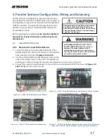
Страница 17: ... the following steps for each amplifier in your system to install the ballast resistors for Parallel System setup Before preparing the amplifiers make sure the amplifier is turned off for at least 3 5 minutes and the AC mains are disconnected 4 1 Install Ballast Resistors 4 1 1 Mount and Connect Ballast Resistor Locate the bracket mounted ballast resistor s in the 1 Ballast Resistor Kit Position t...

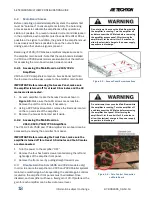
Страница 18: ...the Access Panel and set it aside 3 4 2 2 Accessing the Main Board on 2110 2120 7548 7796 Amplifiers The 2110 2120 7548 and 7796 amplifier s main board can be accessed by removing the amplifier front panel IMPORTANT Before removing the Front Panel make sure the amplifier is turned off for at least 3 5 minutes and the AC mains are disconnected 1 Turn the power to the amplifier OFF 2 Remove the four...

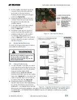
Страница 19: ...se resistors can be mounted to a header or soldered directly to the pins 4 4 Parallel System Balancing Complete the following procedures to balance your parallel amplifier system 4 5 Connect for Balancing For each amplifier in your system connect 1 a leg of the black output cable found in the Parallel Wiring Kit to one of the amplifier s output connectors labeled COM 2105 7224 or SAMPLED COMMON 21...

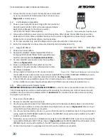
Страница 20: ...UT to COM or SAMPLED COMMON to verify that the DC offset of each amplifier is less than 5 mVdc See Figure 4 11 If the DC offset for any amplifier is greater than 5 mVdc adjust each amplifier using the Amp Offset R65 6 on the amplifier main board Adjust each amplifier s DC offset to read as closely as possible to zero 4 8 Wire and Connect Parallel Inputs IMPORTANT FOR 2105 and 7224 PARALLEL SYSTEMS...

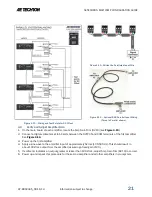
Страница 21: ...rst amplifier 3 Apply a sine wave to the amplifier input of approximately 5Vrms 100 500 Hz This should result in 4 about 100Vrms output from the amplifier assuming a fixed gain of 20 If voltmeter indicates an output greater or lesser than 100 Vrms adjust Amp Gain Trim R210 to correct 5 Power up and repeat this procedure for the second amplifier and all other amplifiers in your system 6 Figure 4 13...

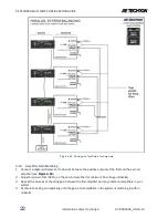
Страница 22: ...irst and the second 1 amplifier see Figure 4 15 Adjust Amp Gain Trim R210 on the second amplifier for minimum AC voltage millivolts 2 Repeat the process of checking gain between the first amplifier and any additional amplifiers in your 3 system Continue checking and adjusting until the gain of all amplifiers in the system is matching to within 4 millivolts Figure 4 14 Wiring and Test Points for Am...

Страница 23: ...AE TECHRON MULTI AMP CONFIGURATION GUIDE 97 8002465_09 19 14 Information subject to change 23 Figure 4 15 Wiring and Test Points for Gain Matching ...

Страница 24: ...el required for your 4 application 4 12 Verify Current Sharing Power down the amplifiers 1 Connect your load to the two output cables Connect the positive terminal of your load to the red cable 2 connected to the amplifier ballast resistors Connect the negative terminal of your load to the black cable connected to the amplifier COM terminals Check to ensure that all system wiring has been correctl...

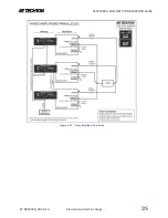
Страница 25: ...AE TECHRON MULTI AMP CONFIGURATION GUIDE 97 8002465_09 19 14 Information subject to change 25 Figure 4 17 Three Amplifiers Paralleled ...

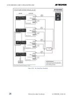
Страница 26: ...AE TECHRON MULTI AMP CONFIGURATION GUIDE 26 Information subject to change 97 8002465_09 19 14 Figure 4 18 Four Amplifiers Paralleled ...

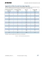
Страница 27: ...ching requirements of wire gauge and continuous duty amperage limits Minimum value for insulated wire in free air i e not bundled Figure A 1 Wire Current Carrying Capacity Chart Continuous Duty Current Amperes American Wire Gauge AWG Diameter mm Diameter Mils 001 in 200 000 10 40 410 175 00 9 27 365 150 0 8 25 325 125 1 7 35 289 100 2 6 54 258 80 4 5 19 204 60 6 4 12 162 46 8 3 26 128 33 10 2 59 1...

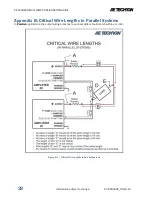
Страница 28: ...formation subject to change 97 8002465_09 19 14 Appendix B Critical Wire Lengths in Parallel Systems In Parallel applications the output wiring branches to each amplifier should match within inch Figure B 1 Critical Wire Lengths in Parallel Systems ...

Страница 29: ...ssistance in determining the requirements for your system IMPORTANT In a paralleled system it is important to control the lengths of output cables Output cables should be between 2 5 and 4 0 feet in length and the lengths of each leg of the output cables should match within 1 4 inch See Appendix B Critical Wire Lengths for information on critical cable lengths for paralleled systems Build two cabl...

Страница 30: ...ed for the Interlock connections This section describes how to build your own DB 25 cable if you so choose Using DB 25 connectors and light gauge single conductor shielded wire build a cable as shown in 1 Figure D 1 On each connector connect to Pin 4 2 On one of the end DB 25 connectors attach the shield to Pin 17 Label this connector for use on 3 Amplifier 1 in the system Figure D 1 DB 25 Cable W...

Страница 31: ...a 2 Phillips screwdriver remove the 8 screws 2 located on the top and side of the amplifier Remove the Access Panel and set it aside 3 Accessing the Main Board on 2110 2120 7548 7796 Amplifiers The 2110 2110 7548 or 7796 amplifier Main Board can be accessed by removing the amplifier front panel Turn the power to the amplifier OFF 1 Remove the four hex head screws located along the left 2 and right...

Страница 32: ...ld be returned to the factory defaults Stand alone amplifiers can operate with jumpers J4 Balanced Unbalanced and J5 Ground Lifted Chassis Ground set to either selection depending on the user s preference Jumpers J12 and J13 Slave Phase Inversion are not active when a SIM BNC OPTOC card is configured for stand alone master use so the setting of this jumpers will not affect stand alone operation 21...

Отзывы: