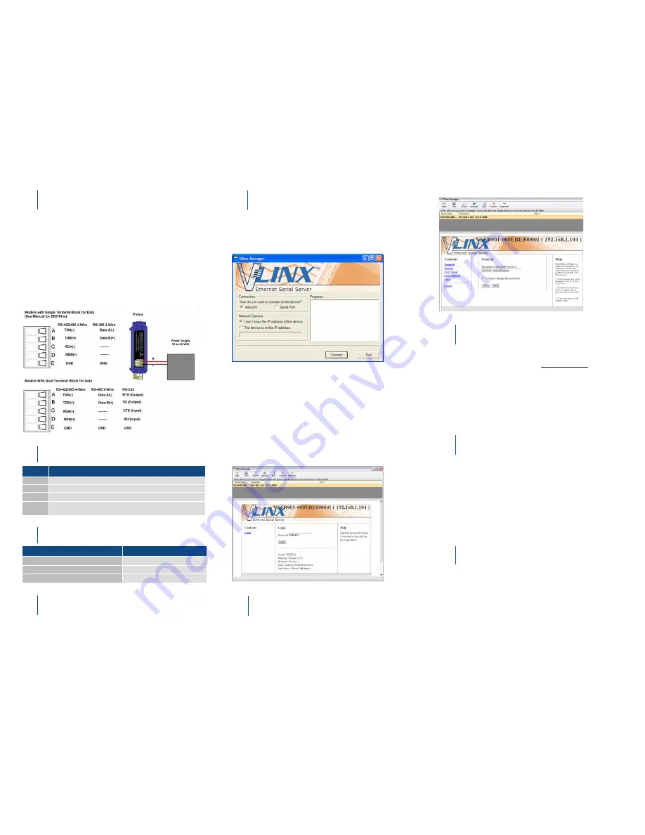
Install the Hardware
Install Vlinx Manager Software
LED Status
1
4
2
1.
Connect a 10-48 VDC (58VDC max.) power supply (6W
required).
2.
Connect the network cable from the serial server to a network
drop using a standard network cable.
3.
Connect the serial device(s):
• RS-232 with DB9: straight-through for DCE device, null
modem for DTE device.
• RS-232/422/485 with terminal blocks. See Appendix D in
user manual for pinouts.
UL Installation - See Step #13 for more information.
1.
Insert the included CD and it should autostart.
2.
Follow the prompts to install the Vlinx Manager software.
Note
: Be sure you have administrative rights & disable firewalls.
Set Up Vlinx Manager Software
5
1.
Open Vlinx Manager, by clicking:
Start > Programs > B&B Electronics > Vlinx > Vlinx Man-
ager > VESR Serial Server
The Discovery page opens.
Log In
6
1.
Click
Login
. (Password is blank from factory.)
The General page appears.
LED
STATUS
Ready
Blinks if system is operating correctly.
Port 1
ON indicates serial port open; blinks when data is present on serial port.
Port 2
Same as Port 1. (Present on 2-port units only.)
Link
ON indicates Ethernet operating in 100BaseTX;
Blinks when data is present on Ethernet link.
Mode Switch
3
HOLD MODE SWITCH IN for...
RESULT
0 to 2 seconds
Initiates a Hardware Reset.
2 to 10 seconds
Enters Console Mode.
Over 10 seconds
Reset to Factory Defaults.
2.
To configure via the network, select
Network
.
3.
If you know the IP address, select
“The device is at this ad-
dress”,
and type in the address. If not, select
“I don’t know the
IP address of the device.”
4.
Click
Connect
.
OR...Set Up the Web Interface:
1.
Open a browser and type the IP address of the serial server in
the Address Bar.
2.
When the serial server is found, the Configuration window
appears.
Set Up Network
7
• The serial server is set at the factory to receive an IP assign-
ment from a DHCP server. If a DHCP server is not available
on your network, it will default to
169.254.102.39.
• If this address does not work with your PC, change your
network settings to:
• IP Address = 169.254.102.1
• Subnet Mask = 255.255.255.0
• Default Gateway = 169.254.102.100
Note
: If you need different settings, refer to User Manual, Chapter 4.
Set Up Serial Port Parameters
8
1.
Click
Port 1 Serial
to open the Serial Port Parameters page.
Select the type of serial connection between the serial server
and the serial device (RS-232, RS-422, RS-485 2-wire, or
RS-485 4-wire).
2.
Select the Baud Rate, Data Bits, Stop Bits, Parity and Flow
Control needed to communicate with the serial device.
3.
If your serial server is 2 port, select the next port in the de-
scription box, then repeat the previous steps.
4.
Click
Next
.
Set Up Port Network Parameters
9
1.
Click
Port 1 Network
to open the Port Network Parameters
page.
2.
Select the type of network protocol you want to use: TCP,
UDP, VCOM or Paired Mode.
3.
If you select TCP, select whether the serial server will oper-
ate as a Client or Server, then configure the required IP ad
-
dress, port numbers and other related parameters.
4.
If you select UDP, configure the IP addresses, ports and
other related parameters for the devices you want to receive
from and send to.


