


PCM-9362 User Manual
10
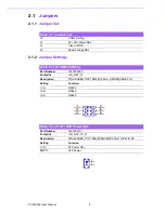
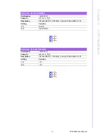
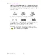
2.1.3
Jumper Description
Cards can be configured by setting jumpers. A jumper is a metal bridge used to close
an electric circuit. It consists of two metal pins and a small metal clip (often protected
by a plastic cover) that slides over the pins to connect them. To close a jumper, you
connect the pins with the clip. To open a jumper, you remove the clip. Sometimes a
jumper will have three pins, labeled 1, 2 and 3. In this case you would connect either
pins 1 and 2, or 2 and 3.
The jumper settings are schematically depicted in this manual as follows.
A pair of needle-nose pliers may be helpful when working with jumpers. If you have
any doubts about the best hardware configuration for your application, contact your
local distributor or sales representative before you make any changes.
Generally, you simply need a standard cable to make most connections.
Warning!
To avoid damaging the computer, always turn off the power supply
before setting jumpers. Clear CMOS. Before turning on the power sup-
ply, set the jumper back to 3.0 V Battery On.
Содержание PCM-9362 Series
Страница 8: ...PCM 9362 User Manual viii...
Страница 14: ...PCM 9362 User Manual 6...
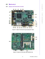
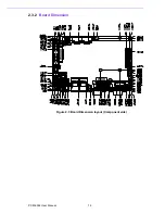
Страница 24: ...PCM 9362 User Manual 16 2 3 2 Board Dimension Figure 2 3 Board Dimension layout Component side...
Страница 26: ...PCM 9362 User Manual 18...
Страница 27: ...Chapter 3 3 BIOS settings...
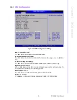
Страница 35: ...27 PCM 9362 User Manual Chapter 3 BIOS settings 3 3 5 ACPI Settings Figure 3 8 ACPI Settings...
Страница 50: ...PCM 9362 User Manual 42 3 7 Advanced Chipset Settings Figure 3 23 Advanced Chipset Settings...
Страница 56: ...PCM 9362 User Manual 48...
Страница 57: ...Chapter 4 4 S W Introduction Installation...
Страница 69: ...Appendix A A PIN Assignments...
Страница 98: ...PCM 9362 User Manual 90 17 GND 18 A02 19 A01 20 A00 21 D00 22 D01 23 D02 24 NC 25 CD2 26 CD1 Table A 32 CN32 CF...
Страница 99: ...91 PCM 9362 User Manual Appendix A PIN Assignments...


