MIC-770 Startup Manual 3
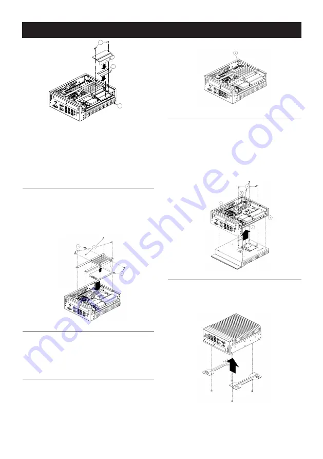
1. Undo 4 screws and remove the bottom cover.
2. Undo 4 screws to remove the storage tray.
3. Undo 3 screws to remove memory thermal cover.
4. Affix thermal pad (P/N: 1990019498N000) on memory
and assemble memory.
Note :
Thermal pad and memory thermal cover must
be fully mated and compacted.
Storage Installation
1. Undo 4 screws and remove the bottom cover
2. Undo 4 screws to remove storage tray.
3. Secure the 4 x screws (P/N:1930002235)
4. Assemble SATA cable/power cable and replace stor-
age tray; secure with 4x screws.
5. Replace the bottom cover.
Mini-PCIE Installation
MIC-770 supports one full size Mini-PCIE.
1. Undo 4 screws and remove the bottom cover.
2. Install the module in the Mini-PCIe socket and secure
with screws.
3. Replace bottom cover and secure with screws.
Internal USB 2.0 Installation
1. Undo 4 screws and remove the bottom cover.
2. Loosen the screw and adjust bracket size in accor-
dance with USB dongle size.
3. Install USB dongle in the first socket. Only first socket
has this function.
4. Secure with screw and replace bottom cover and
attach with screws.
3
3
4
CPU Installation
1. Undo 4 screws and remove the bottom cover.
2. Undo 4 screws to remove storage tray.
3. Undo 4 screws in the corner of chassis.
4. Undo 4 screws around CPU to release AL heatsink.
5. Remove AL heatsink and install CPU.
6. Smear thermal grease onto CPU.
7. Replace AL heatsink, storage tray and bottom cover.
Mounting Kit Installation
1. Take the mounting kit from accessory box.
2. Secure the 4x screws (P/N: 1930007259-01, M4x4L
F/S D=8.5 H=1.5 (2+) ST/H BZn-NK) and install system
on table.
Simple Maintenance Process (Cont.)


