


18
BASE+3
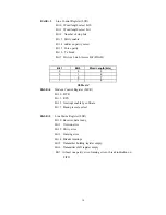
Line Control Register (LCR)
Bit 0 Word length select bit 0
Bit 1 Word length select bit 1
Bit 2 Number of stop bits
Bit 3 Parity enable
Bit 4 odd/even parity select
Bit 5 Force parity
Bit 6 Tx break
Bit 7 Divisor Latch Access Bit (DLAB)
Table 4-4
BASE+4
Modem Control Register (MCR)
Bit 0 DTR
Bit 1 RTS
Bit 3 Interrupt enable by software
Bit 7 Baud prescale select
BASE+5
Line Status Register (LSR)
Bit 0 Receiver data ready
Bit 1 Overrun error
Bit 2 Parity error
Bit 3 Framing error
Bit 4 Breaks interrupt
Bit 5 Transmitter holding register empty
Bit 6 Transmitter shift register empty
Bit 7 At least one parity error, framing error or break indication on
FIFO
Bit 1
Bit 0
Word Length (bits)_
0
0
5
0
1
6
1
0
7
1
1
8
Содержание MIC-3620
Страница 3: ...1 Chapter 1 Introduction ...
Страница 6: ...4 ...
Страница 7: ...5 2 Hardware Configuration Chapter ...
Страница 12: ...10 ...
Страница 13: ...11 3 Pin Assignment Wiring Chapter ...
Страница 16: ...14 ...
Страница 17: ...15 4 Register structure format Chapter ...


