Advantech IPC-622MS Скачать руководство пользователя страница 6


 IPC-622MS   User's Manual   3

2.1  Remo

ve the cover

Chapter 2  System Setup

Setting up your IPC-622MS  requires only a screwdriver and a small amount of time. Before you begin,

you should also gather together all of the cards you plan to install, as well as the disk drives you plan

to use.
The lockable door is located on the lower  chassis front cover providing access to the control panel. This

offers protection and for disk drive and air filter  against damage and easily  access. The control panel

functions include Power on/off switch , CPU reset switch and alarm reset switch  and  five LED

indicators to assist in monitoring system status. On the rear panel there is a Ground point (earthing point)

located on the bottom right hand corner. This provides an earth for the whole system and is attached via

a screw.

WARNING:

Disconnect all power from the chassis before you install
the CPU cards. Unplug the power cord from the wall,
don't  just turn off the power switch. If you are not sure
what to do, take the job to an experienced professional.

CAUTION:

When pull-out the disk drive, it will cause the IDE / SCSI drives'
cable wiring disconnected. Be sure all the cables are well-con-
nected before slide back the disk drive bay.

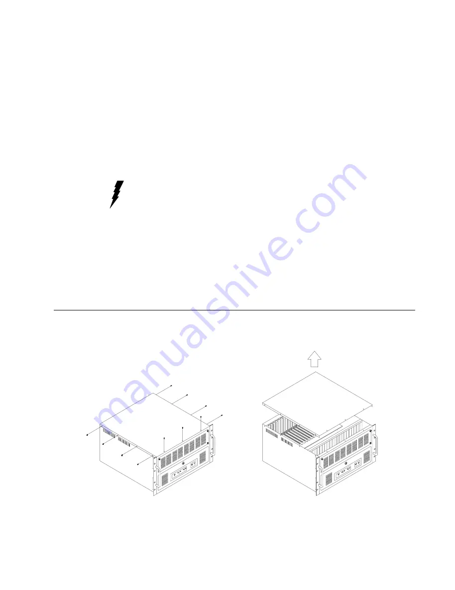
2.1  Remove the cover

There are screws near the top along the sides secure the cover to the chassis. Remove them, and then

slide the cover  toward the rear  chassis. See figure 2.1 below:

All manuals and user guides at all-guides.com

Содержание IPC-622MS

Страница 1: ...IPC 622MS Industrial PC Chassis All manuals and user guides at all guides com...

Страница 2: ...ual is intended to be accurate and reliable However Advantech Co Ltd assumes no responsibility for its use nor for any infringements of the rights of third parties which may result from its use Acknow...

Страница 3: ...able wiring schematic 6 2 6 Cable wiring schematic 7 2 7 The rubber for card vibration damped 8 Chapter 3 Fault Resilient Function 9 3 1 Introduction 9 3 2 Fault detection and alarm notification 9 3 3...

Страница 4: ...e dust and dirt A lockable door protects drives and switches from tampering and particles 1 2 Specifications General Construction Heavy duty steel Disk drive capacity Six 3 5 disk drives Cooling syste...

Страница 5: ...Operating temperature 41 to 95o F 5 to 35o C Relative humidity 10 to 85 35o C Storage Temperature 13 to 140o F 25 to 60o C 0 to 95 relative humidity Safety UL C UL Listed EMI FCC Class A Fault Detect...

Страница 6: ...system status On the rear panel there is a Ground point earthing point located on the bottom right hand corner This provides an earth for the whole system and is attached via a screw WARNING Disconnec...

Страница 7: ...e filter The filter is located on the front upper chassis Under continuous use the filter should be replaced about once a month To replace the filter refer to figure 2 4 below and do as the following...

Страница 8: ...sides Remove the four outer screws which mount the shock resistant drive bay to the chassis See figure 2 4 below 2 Slide the drive bay toward the front chassis and lift it free of the chassis Remove t...

Страница 9: ...etails of the setting Position 1 ID BIT 3 OPEN OPEN OPEN OPEN Position 2 ID BIT 2 OPEN OPEN OPEN CLOSE Position 3 ID BIT 1 OPEN CLOSE CLOSE OPEN Position 4 ID BIT 0 CLOSE OPEN CLOSE OPEN Position 5 AU...

Страница 10: ...IPC 622MS User s Manual 7 2 6 Cable wiring schematic The following picture is the cable schematic for IPC 622MS 2 7 Cable schematic All manuals and user guides at all guides com...

Страница 11: ...mped The IPC 622MS uses two rubbers on the inside cover of the chassis to ensure the plug in cards are located securely It also offers protection against shock and vibration 2 8 The rubber for cards v...

Страница 12: ...ion The IPC 622MS monitors system hardware for fan failure and high temperature within the chassis Fault conditions are Fan failure Either of the four cooling fans fails High Temperature If the chassi...

Страница 13: ...eset However the alarm indicator will stay red until the fault condition is resolved 3 2 Controls 3 4 Overheating Sensor There is a small PC board the Over Temp board installed on the left interior of...

Страница 14: ...IPC 622MS User s Manual 11 Unit mm Appendix A Passive Backplane PCA 6119P17 17PCI 1PICMG slot Backplane Dimension 420 x 200 mm All manuals and user guides at all guides com...

Страница 15: ...12 IPC 622MS User s Manual Appendix B Exploded Diagram All manuals and user guides at all guides com...

Страница 16: ...IPC 622MS User s Manual 13 All manuals and user guides at all guides com...

Страница 17: ...l cautions and warnings on the equipment should be noted 11 If the equipment is not used for a long time disconnect the equipment from mains to avoid being damaged by transient overvoltage 12 Never po...

Страница 18: ...quipment generates uses and can radiate radio frequency energy and if not installed and used in accordance with the instruction manual may cause harmful interference to radio communications Operation...

Отзывы: