background image


FWA-3140 User Manual --- Page  10

2.


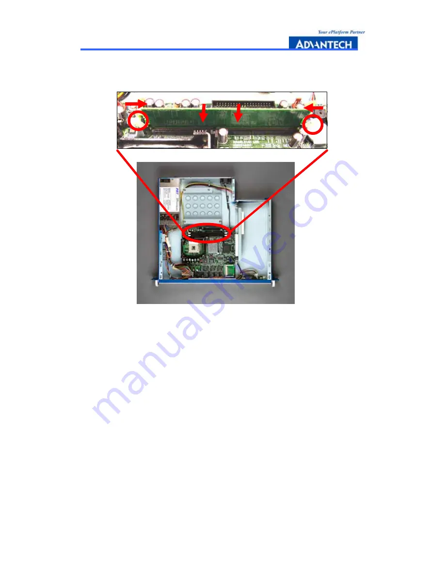
Press the retaining clips inward to lock the DIMM memory module. Installing 
memory module is completed. 


1.

2.

1.

2.

1.

2.


Figure 2-5: Installing Memory Module steps 


2.4 Installing Hard Disk Drive 

 
1.


Unscrew each side of the HDD supporting frame on the chassis and pull it out. 

2.


Put the HDD above the HDD supporting frame and position the screws 
accordingly. 

3.


Screw each side of the HDD supporting frame to fix on the chassis. 

4.


Connect the IDE cable included in the accessory box to the connector on the 
HDD. Make sure that the RED wire on the ribbon should be connected to PIN 1 of 
HDD. 

5.


Connect power connector to the HDD. Installing Hard Disk Drive is completed. 


Содержание FWA-3140

Страница 1: ...Advantech Internet Security Platform FWA 3140 Rackmount Internet Security Platform with 4 Front LAN Ports Dual PCI Expansion Slots LCD Display...

Страница 2: ...hout the prior written permission of the original manufacturer Information provided in this manual is intended to be accurate and reliable However the original manufacturer assumes no responsibility f...

Страница 3: ...t of replacement materials service time and freight Please consult your dealer for more details If you think you have a defective product follow these steps 1 Collect all the information about the pro...

Страница 4: ...manual PDF file If any of these items are missing or damaged contact your distributor or sales representative immediately Technical Support and Sales Assistance If you have any technical questions ab...

Страница 5: ...fications 2 1 4 Dimensions 4 1 5 Model List 5 2 System Setup 6 2 1 Removing the cover 7 2 2 Installing Central Processing Unit CPU 8 2 3 Installing Memory Module 9 2 4 Installing Hard Drive 10 2 5 Ins...

Страница 6: ...gure 2 3 Top view of FWA 3140 8 Figure 2 4 Installing Central Processing Unit steps 9 Figure 2 5 Installing Memory Module steps 10 Figure 2 6 Installing Hard Disk Drive steps 11 Figure 2 7 Installing...

Страница 7: ...FWA 3140 User Manual Page 1 1 General Information...

Страница 8: ...sing LAN ports in the front panel There are two LED Indicators which monitor power and HDD activities For easy access the front panel has a 9 pin RS 232 serial port for local system management mainten...

Страница 9: ...for Power HDD CompactFlash Socket x1 LCD Display Module x1 Adapter Power Requirement Input ATX PS AC 90 264 V 47 63 Hz full range Output 250W Operating Environment Operating Temperature 0 40 C 32 104...

Страница 10: ...FWA 3140 User Manual Page 4 1 4 Dimensions Figure 1 1 FWA 3140 dimensions Figure 1 2 Outlook of FWA 3140...

Страница 11: ...ting one LAN Bypass function FWA 3140 B 1U rackmount Internet security platform Dual 32 bit 33 MHz PCI expansion slots LCD display module two 10 100 Fast Ethernet and two 10 100 1000 Gigabit Ethernet...

Страница 12: ...FWA 3140 User Manual Page 6 2 System Setup...

Страница 13: ...re one is power LED and another is HDD LED On the rear panel there is a power switch located on the top right hand corner Four LAN ports LCD display module RS 232 Console port LEDs Power x 1 HDD x 1 P...

Страница 14: ...that its marked corner golden cut edge on the CPU upper corner matches the base of the socket lever Insert the CPU into the socket Do not force the CPU into the socket Then push down the socket lever...

Страница 15: ...odule Please note that FSB 533 Pentium 4 processor will support DDR333 DDR266 memory module and FSB 400 Pentium 4 processor will only support DDR266 memory module 1 Unlock a DIMM socket by Align the n...

Страница 16: ...the HDD supporting frame on the chassis and pull it out 2 Put the HDD above the HDD supporting frame and position the screws accordingly 3 Screw each side of the HDD supporting frame to fix on the cha...

Страница 17: ...5 2 1 1 3 4 5 3 4 5 2 2 Figure 2 6 Installing Hard Disk Drive steps 2 5 Installing Compact Flash 1 Position a CompactFlash disk accordingly in the CompactFlash disk socket and push it inward Installi...

Страница 18: ...ed as Figure 2 8 When system shuts down LAN1 LAN2 will connect directly to avoid network broken Network appliance software Rx Tx Rx Tx Rx Tx Rx Tx Network appliance software Rx Tx Rx Tx Rx Tx Rx Tx Ne...

Страница 19: ...6 J4 LAN Bypass Control 1 3 WATCH DOG Default 1 3 WATCH DOG Default 3 5 LAN Bypass Off 3 5 LAN Bypass Off N C LAN Bypass On N C LAN Bypass On 2 4 AUTO On Default 2 4 AUTO On Default 4 6 GPIO Control 4...

Страница 20: ...FWA 3140 User Manual Page 14 Figure 2 10 Setting LAN Bypass function from BIOS...

Страница 21: ...FWA 3140 User Manual Page 15 A Pin Assignments APPENDIX...

Страница 22: ...E Bus Connector CN2 CN4 FAN power Connector CN3 CN6 CN8 FAN power Connector CN5 Floppy Connector CN9 Switch and LED CN14 Parallel Port Connector CN15 CN34 USB Port Connector CN16 PS 2 KB and Mouse Con...

Страница 23: ...22 WRTPRT 23 GND 24 RDDATA 25 GND 26 SIDESLT CN9 PIN NAME PIN NAME 1 Power SW 2 Power SW 3 Reset SW 4 Reset SW 5 Power LED 6 Power LED 7 Standby 8 Standby 9 LAN1 LED 10 LAN1 LED 11 LAN2 LED 12 LAN2 L...

Отзывы: