


Non-standard STO delay times are provided by special factory order. In this case, the non-standard STO
delay time is indicated by a label placed on the slice amplifier’s main connector (STO DELAY = xx sec).
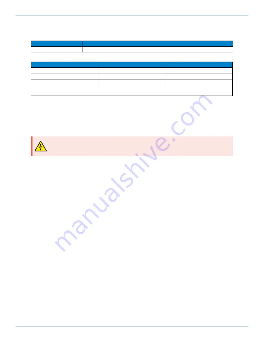
Table 2-30:
STO Signal Delay
Value
STO Time Delay
450-550 msec
Table 2-31:
Motor Function Relative to STO Input State
STO 1
STO 2
Motor Function
Unpowered
Unpowered
No force/torque
Unpowered
(1)
Powered
(1)
No force/torque
Powered
(1)
Unpowered
(1)
No force/torque
Powered
Powered
Normal Operation
1. This is considered a Fault Condition since STO 1 and STO 2 do not match. Refer to
2.4.3. STO Startup Validation Testing
Verify the state of the STO 1 and STO 2 channels by manually activating the external STO hardware. Each
STO channel must be tested separately in order to detect potential short circuits between the channels.
The current state of the STO 1 and STO 2 inputs is shown in the Status Utility. A “–” indicates that the
STO input is powered by a high voltage level (24 V). An “ON” indicates that the voltage source has been
removed from the input (open circuit or 0 V), and that the STO channel is in the safe state.
DANGER
: The STO circuit does not remove lethal voltage from the motor terminals. AC
mains power must be removed before servicing.
2.4. Safe Torque Off Input (STO)
XC4 Hardware Manual
64
www.aerotech.com
Содержание Automation1 XC4
Страница 1: ...Revision 2 01 Automation1 XC4 PWM Digital Drive HARDWARE MANUAL...
Страница 10: ...This page intentionally left blank EU Declaration of Conformity XC4 Hardware Manual 10 www aerotech com...
Страница 12: ...This page intentionally left blank Agency Approvals XC4 Hardware Manual 12 www aerotech com...
Страница 14: ...This page intentionally left blank Safety Procedures and Warnings XC4 Hardware Manual 14 www aerotech com...
Страница 16: ...This page intentionally left blank Installation Overview XC4 Hardware Manual 16 www aerotech com...
Страница 23: ...1 2 2 Dimensions Figure 1 3 Dimensions XC4 Hardware Manual 1 2 2 Dimensions www aerotech com 23...
Страница 24: ...Figure 1 4 Dimensions EB1 1 2 2 Dimensions XC4 Hardware Manual 24 www aerotech com...
Страница 71: ...Figure 2 36 PSO Interface XC4 Hardware Manual 2 5 Auxiliary I O Connector www aerotech com 71...
Страница 92: ...Figure 3 2 Digital Outputs Schematic EB1 3 1 Digital Outputs EB1 XC4 Hardware Manual 92 www aerotech com...
Страница 103: ...Figure 4 2 Two Axis Joystick Interface to the I O board XC4 Hardware Manual 4 1 Joystick Interface www aerotech com 103...
Страница 108: ...This page intentionally left blank 5 2 Fuse Specifications XC4 Hardware Manual 108 www aerotech com...
Страница 112: ...This page intentionally left blank Appendix B Revision History XC4 Hardware Manual 112 www aerotech com...
Страница 120: ...Index XC4 Hardware Manual This page intentionally left blank 120 www aerotech com...


