AIMB-705 Startup Manual 3
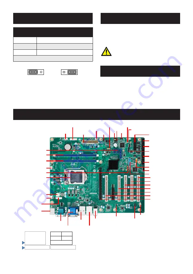
JUSB_2: USB power source switch b5V and
+5V_ DUAL for onboard USB ports
Closed Pins
Result
1-2
*USB +5V_DUAL Power
2-3
USB +5V Power
* Default
*USB +5 V_DUAL Power USB +5 V Power
1
2
3
1
2
3
The CD disc contains a driver installer program that will
lead you through the installation of various device drivers
needed to take full advantage of your motherboard.
Caution!
The computer is supplied with a battery-pow-
ered realtime clock circuit. There is a danger
of explosion if battery is incorrectly replaced.
Replace only with same or equivalent type
recommended by the manufacturer. Discard
used batteries according to manufacturer’s
instructions.
This device complies with the requirements in Part 15 of
the FCC rules. Operation is subject to the following two
conditions:
1. This device may not cause harmful interference.
2. This device must accept any interference received,
including interference that may cause undesired
operation.
Jumpers and Connectors (Cont.)
Software Installation
Declaration of Conformity
Board Layout
KBMS1
DIMMB1
DIMMA1
SYSFAN1
VOLT1
EATXPWR1
PSON1
JWDT1+JOBS1
JFP3
JFP1+JFP2
SMBUS1
GPIO1
LPT1
SPI_CN1
SATA0 ~ SATA3
COM3
COM4
COM5
COM6
LPC1
USB5
USB910
USB3_12
CPU1
CPUFAN1
PCI1
PCI2
PCI3
PCI4
PCIEX4_1
PCI5
PCIEX16_1
FPAUD1
LANLED1
SPDIF_OUT1
AUDIO1
AUDIO2
LAN1_USB3_34
LAN2_USB34
VGA1+DVI1
COM12
SYSFAN2
KBMS2
ATX12V1
JCASE1
JCMOS1
3 6 9 12
2
5
8
11
PWRSW
RESET
HDDLED
SNMP
JFP1
&
2
5
8
11
1 4 7 10
HDDLED
SM_BUS
SPEAKER
JFP2
&
PWRLED & KEYLOCK
1 2 3 4 5
JFP3
Figure 1: Board Layout: Jumper and Connector Locations


