Advantage Engineering Maximum Скачать руководство пользователя страница 35

MK Series Portable Chiller :  Air-Cooled  :  HE INSTRUMENT

Page: 35

ADVANTAGE ENGINEERING, INC.

525 East Stop 18 Road Greenwood, Indiana 46142 

317-887-0729    Fax: 317-881-1277

Service Department Fax:  317-885-8683

Email: [email protected]
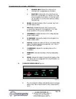
2.

SOLID YELLOW:

if the process temperature

deviates outside the programmed setting.

3.

FLASHING RED:

If the temperature remains

out of band for 90 seconds or more. The
alarm circuit is activated.

b.

FLOW:

illuminates according to the current state of

flow:

1.

SOLID GREEN:

the process flow is within

the programmed parameters. 

2.

FLASHING RED:

if the flow deviates

beyond the programmed parameters.

3.

SOLID RED:

if the flow had once deviated

but is now within the programmed
parameter.

c.

WATER LEVEL:

1.

SOLID GREEN:

the reservoir water level is

at proper operating level. 

2.

FLASHING RED:

the reservoir water level

has dropped below the proper operating
level. The automatic water make-up system
has activated to restore the water level.
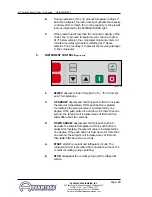
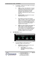
I.

MACHINE STATE DISPLAY 

(figure 3.3H)

1.

Machine status lights indicate the operating status of
several machine components. Further operational
information for each component is located in section 6.0
Consult the section 4.0 for troubleshooting information. For
each component:

a.

SOLID GREEN:

indicates the component is

currently at an acceptable run condition.

Figure 3.3H

Содержание Maximum

Страница 1: ...E Covering Air Cooled models from 5 to 30 tons with HE Instruments ADVANTAGE ENGINEERING INC 525 East Stop 18 Road Greenwood IN 46142 317 887 0729 fax 317 881 1277 Service Department fax 317 885 8683 www AdvantageEngineering com e mail service AdvantageEngineering com ...

Страница 2: ......

Страница 3: ...DELS COVERING INSTALLATION OPERATION MAINTENANCE ADVANTAGE ENGINEERING INC 525 East Stop 18 Road Greenwood IN 46142 317 887 0729 fax 317 881 1277 Service Department fax 317 885 8683 website www AdvantageEngineering com e mail service AdvantageEngineering com ...

Страница 4: ...denser 13 2 5 Electrical connection 14 3 0 OPERATIONS 17 3 1 General 18 3 2 Start up operations procedure 19 3 3 Instrument operation 24 3 4 Shut down procedure 31 4 0 TROUBLESHOOTING 33 4 1 Sensors 34 4 2 Process evaporator pump 34 4 3 Compressor 34 4 4 Low flow 34 4 5 Blower fan 34 4 6 High pressure 35 4 7 Low pressure 35 4 8 Water level 35 4 9 Freezestat 36 4 10 Oil pressure 36 4 11 Crankcase h...

Страница 5: ...5 7 1 Mechanical schematic 5 7 5 10 tons 56 7 2 Mechanical schematic 15 20 25 30 57 7 3 Physical 5 tons 58 7 4 Physical 7 5 10 tons 59 7 5 Physical 15 20 25 30 tons 60 7 6 Duct schematic for air cooled chillers 61 7 7 Electrical 62 8 0 APPENDIX 63 8 1 Specifications 64 8 2 Model and suffix coding 65 8 3 Operations below 48 F 66 8 4 Water quality control 67 8 5 Inhibited propylene glycol 68 8 6 Sen...

Страница 6: ...Page 6 THIS PAGE INTENTIONALLY BLANK ...

Страница 7: ...GINEERING INC 525 East Stop 18 Road Greenwood Indiana 46142 317 887 0729 Fax 317 881 1277 Service Department Fax 317 885 8683 Email service AdvantageEngineering com 1 0 GENERAL 1 1 INTRODUCTION 1 2 UNIT LOCATION 1 3 EFFICIENCY 1 4 SAFETY 1 5 CLEAN AIR ACT 1 6 MISCELLANEOUS ...

Страница 8: ...ugal blower on models from 15 to 30 tons generates air flow through the condenser to remove heat from the refrigerant system The air cooled condenser on the unit will discharge a maximum of 15 000 BTU s per hour per ton of cooling C The unit must have a minimum entering air temperature of 60 F and a maximum entering air temperature of 95 F for efficient operation D The unit must have a minimum of ...

Страница 9: ... a class 2 substance B Effective July 1 1992 it is unlawful for any person in the course of maintaining servicing repairing or disposing of refrigeration equipment to knowingly vent or otherwise dispose of any class 2 substance used as a refrigerant in the manner which permits such substance to enter the atmosphere C De minimis releases associated with good faith attempts to recapture reclaim or r...

Страница 10: ...vantageEngineering com MK 10A shown Air Cooled Condenser Caster Stainless Steel Frame Electrical Cabinet Instrument LE shown Pressure Gauges Protective Fan Shroud Caster Liquid Receiver Compressor Liquid Line Solenoid Refrigerant Site Glass Flow Switch Fan Motor Protective Fan Shroud Air Discharge Pressure Gauges not visible Instrument not visible Hot Gas Bypass Valve Pump Expansion Valve Insulate...

Страница 11: ... East Stop 18 Road Greenwood Indiana 46142 317 887 0729 Fax 317 881 1277 Service Department Fax 317 885 8683 Email service AdvantageEngineering com 2 0 INSTALLATION 2 1 GENERAL 2 2 TO AND FROM PROCESS CONNECTIONS 2 3 WATER SUPPLY CONNECTION 2 4 AIR COOLED CONDENSER 2 5 ELECTRICAL CONNECTION ...

Страница 12: ...NNECTIONS A Connect the TO PROCESS to the water in manifold on the mold or process B Connect the FROM PROCESS port to the water out port on the process manifold C Process water piping circuitry should be designed to avoid an excessive use of elbows and or lengths of pipe or hose If hose is the material of choice avoid tight twists or curls and excessive lengths D Valves and filters may be installe...

Страница 13: ...s and eventual shut down on the high pressure safety switch In such cases a water assist unit may be necessary for operations Air temperatures below 60 F may result in below normal condensing pressures and poor condensing In such cases a low ambient damper assembly is required Check with the ADVANTAGE service department for more information on operating with ambients air temperatures above 95 F or...

Страница 14: ...ser intake air temperature will be less than 60 F See figure 2 4D to the right G All air cooled units must have all enclosure panels in place before operating compressor Air will not be drawn through the condenser coil if they are not in place This will cause the compressor to lockout on the high pressure safety fault 2 5 ELECTRICAL CONNECTION A NEMA 1 MODELS 1 Electrical power supply requirements...

Страница 15: ... unit s voltage requirements WARNING Do not connect the unit to a voltage supply source not equal to the unit s voltage requirements as specified on the unit s data plate Use of incorrect voltage will void the unit s warranty and cause a significant hazard that may result in serious personal injury and unit damage 2 Appropriate conduit and fittings should be selected which will maintain the integr...

Страница 16: ... installed transformer An inline control circuit fuse is provided D GENERAL 1 Make certain all ground connections to the unit are properly affixed 2 Make certain power conductor disconnecting means and fusing are properly sized according to the unit s power supply requirements E INFORMATION REGARDING PHASING OF SCROLL COMPRESSORS 1 All portable chillers that have pumps the compressor s will be set...

Страница 17: ...GE ENGINEERING INC 525 East Stop 18 Road Greenwood Indiana 46142 317 887 0729 Fax 317 881 1277 Service Department Fax 317 885 8683 Email service AdvantageEngineering com 3 0 OPERATIONS 3 1 GENERAL 3 2 START UP OPERATIONS PROCEDURE 3 3 INSTRUMENT OPERATION 3 4 SHUT DOWN ...

Страница 18: ...HOULD BE APPLIED TO THE UNIT FOR AT LEAST 12 HOURS OR UNTIL THE BOTTOM OF THE COMPRESSOR IS WARM TO THE TOUCH If the power has been disconnected more than two hours the power should be applied for six hours before restarting Power should be applied to the unit continuously except for service purposes The crankcase heater should be checked for proper operation on a regular basis UNITS WITH SCROLL C...

Страница 19: ...s manual for more information 3 FOR AUTOMATIC FILL engage the water supply to unit The level switch will activate the make up solenoid figure 3 2A which will open and the water supply will fill the reservoir tank The WATER LEVEL light figure 3 2B on the instrument will flash red while the make up solenoid valve is open When the reservoir tank is filled the WATER LEVEL light will illuminate green D...

Страница 20: ...djust the setpoint to 70 F to prevent the compressor from activating during this procedure b Remove all necessary cover panels to access the pump motor Note that the electrical power is engaged at this point and caution must be observed while the electrical supply is engaged and cabinet panels are removed and opened c Locate the electric motor figure 3 2D The electric motor can be identified when ...

Страница 21: ...wer supply is disengaged reverse any two power leads of the power cord at the disconnect terminals c Note reversing any two power leads of the power cord will correctly phase the power supply to the unit The operator must reverse the power leads at the disconnect switch only and not at the power entry terminals on the unit s electrical panel The unit s internal electrical system wiring is phased c...

Страница 22: ...serve the COOLANT pressure gauge for steady readout Two items the operator for look for are low flow or excessive flow conditions 3 LOW FLOW If the LOW FLOW light figure 3 2G is flashing red be sure all process valves are open If all process valves are open then a low flow condition exists a To operate under a low flow condition it is necessary to install a flow bypass system in the process circui...

Страница 23: ...ad circuit has tripped the operator must manually reset the overload relay figure 3 2I before operations can continue This is done by opening the electrical panel cover identifying the reset lever on the overload relay and pushing the reset lever in until the overloads are reset evidenced by a clicking sound as the overloads reset 4 The instrument displays the process flow rate in the FLOW display...

Страница 24: ...necessary follow proper shut down and disconnect procedures to install a throttling valve c With the throttling valve installed fully close the valve and then engage the pump motor Slowly open the throttling valve and monitor the indicated flow rate until the flow rate is below the pump s maximum flow rate At this point the process flow is now correctly adjusted The valve should remain in the posi...

Страница 25: ...ted in an effort to restore the reservoir to the proper operating level If the reservoir does not fill in a reasonable amount of time check the operation of the make up solenoid valve or determine in the water supply valve customer supplied is fully open The water level sight glass is provided to visually check the reservoir level b Probe a possible cause of a probe error is the probe service conn...

Страница 26: ... the overload relay is open the overload relay must be reset before operations can continue An excessive flow condition must be corrected immediately b High pressure switch open a flashing red HI PRESSURE light indicates the refrigerant high pressure switch is open This normally occurs when condensing pressures exceed normal parameters To continue operations the operator must reset the safety swit...

Страница 27: ...ndow Use the UP and DOWN ARROW keys to change the setpoint temperature 4 PRECAUTIONS the instrument is programmed from the factory with a setpoint range of 48 to 70 F To operate below 48 F the addition of inhibited propylene glycol and modification of the safety control settings are required Diligent monitoring of the water glycol solution is mandatory to prevent freezing of the evaporator Freezin...

Страница 28: ...sor C INSTRUMENT CONTROLS figures 3 3B 1 SELECT depress to index through the to from and set point temperatures 2 UP ARROW depress and hold this push button to increase the setpoint temperature If this push button is pressed momentarily the setpoint value is incremented by one degree If the push button is held down for more than one second the setpoint will increase slowly at first and then faster...

Страница 29: ...cess temperature display was selected and left in that state a Use the SELECT key to index to the FROM indication lights The from process temperature will be displayed in the TEMPERATURE DISPLAY window 3 C illuminates when the C Celsius temperature display parameter is selected 4 F illuminates when the F Fahrenheit temperature display parameter is selected F is the default setting of the instrumen...

Страница 30: ...ALT large flow sensor selected ton chillers size in tons CAP capacity display selection Prb from process probe calibration LPt low pressure time delay 2 TEMP illuminates when the following parameters are selected SP setpoint temperature tON tonnage display in CAPACITY window PCt percent display in CAPACITY window HI high temperature deviation limit Lo low temperature deviation limit a SP indicates...

Страница 31: ... the to process temperature reaches it 1 30 units selectable e Lo programs the low alarm temperature deviation limit This is the low temperature setting at which an alarm is activated if the to process temperature decreases to it 1 30 units selectable 2 FLOW illuminates when the following parameters are selected LoF low flow limit a LoF programs the low flow value During operations if the flow dec...

Страница 32: ...ay or select C for Celsius temperature display with LPM liters per minute flow display b To show the parameters in the extended display mode the 3 DIP switch must be toggled Refer to section 5 8 for more details c AFL programs the alternate flow sensor selection A YES will set the instrument to the internal flow sensor A NO will set the instrument to the external flow sensor Typically the instrume...

Страница 33: ...rebuild pressure within the time delay Check with the factory service department before altering this parameter F FLOW DISPLAY figure 3 3E 1 The FLOW display shows information concerning the pump generated flow The flow measuring mechanism is installed in the from process water line Typically an internal flow sensor is provided with the chiller In some cases a larger external flow sensor is provid...

Страница 34: ...te percent of capacity display This display is a percent of the chiller s total capacity in current use The display is continuous when the CAP parameter is toggled to the PCt selection The and TONS display will alternate on a 8 second cycle when the CAP parameter is toggled to the ALT selection d TONS illuminates to indicates tonnage display This display is a numeric indication of the chiller s cu...

Страница 35: ...SHING RED if the flow deviates beyond the programmed parameters 3 SOLID RED if the flow had once deviated but is now within the programmed parameter c WATER LEVEL 1 SOLID GREEN the reservoir water level is at proper operating level 2 FLASHING RED the reservoir water level has dropped below the proper operating level The automatic water make up system has activated to restore the water level I MACH...

Страница 36: ...mp motor overload relay See section 3 2 paragraph C 2 for more proper operation of the pump overload relay 4 HI PRESSURE indicates the status of the refrigerant high pressure safety switch 5 LO PRESSURE indicates the status of the refrigerant low pressure safety switch 6 LOW OIL indicates the status of the low oil pressure safety switch This light activates on models with a 15 30 ton semi hermetic...

Страница 37: ...an be silenced by pressing the START key J PRESSURE GAUGES figure 3 4F 1 PROCESS PRESSURE GAUGE indicates process pump pressure 2 REFRIGERANT HEAD PRESSURE GAUGE indicates refrigerant pressure on the discharge side of the compressor The refrigerant head pressure is also the condensing pressure which is critical to equipment efficiency Head pressure on air condensed units will vary with ambient tem...

Страница 38: ...l service AdvantageEngineering com B UNIT SHUT DOWN 1 To shut down the unit without disconnecting from the process Press the stop button Maintain electrical power to the unit at all times except for service purposes 2 To shut down the unit and disconnect from the process a Press the stop button b Disengage the electrical supply to the chiller at the disconnecting device c Disconnect all process li...

Страница 39: ...729 Fax 317 881 1277 Service Department Fax 317 885 8683 Email service AdvantageEngineering com 4 0 TROUBLESHOOTING 4 1 SENSORS 4 2 PROCESS EVAPORATOR PUMP 4 3 COMPRESSOR 4 4 LOW FLOW 4 5 THREE PHASE SUPPLY 4 6 LOW FLOW 4 7 HIGH PRESSURE 4 8 LOW PRESSURE 4 9 WATER LEVEL 4 10 FREEZESTAT 4 11 OIL PRESSURE 4 12 CRANKCASE HEATER 4 13 ELECTRONICS ...

Страница 40: ...amp draw and if overloaded partially close the from process line valve until the amp draw drops to the proper level 4 3 COMPRESSOR A Semi hermetic compressors are protected by an external overload device Klixon switch solid state module etc If the safety switch opens this indicates an overload condition exists B Check for electrical shorts loose wires bad fuses or bad motor starter contacts If the...

Страница 41: ...ed condensing water supply and return lines defective regulator valve on water cooled models or restricted air flow on air cooled models 4 8 LOW PRESSURE A If the refrigerant low pressure safety switch has opened the cause of the problem must isolated and resolved B The switch will automatically reset when the pressure rises above the cut in pressure If this does not occur contact the ADVANTAGE se...

Страница 42: ...stat sensor bulb is located at the evaporator water outlet port If the water out temperature of the evaporator reaches the freezestat setting the switch will open and stop the refrigeration compressor B Check for restricted water flow and add a bypass line if necessary C The setpoint is adjusted too low for the safety switch settings D The freezestat is adjusted incorrectly or is defective 4 11 OI...

Страница 43: ...esigned to be easily removed and replaced if a problem arises B The CPU is mounted inside the electrical enclosure this contains the software and various electronic components which make the HE instrument work Note the CPU is not a field repairable part It is designed to be easily removed and replaced if a problem arises Do not attempt to open the enclosure box as this will void the warranty The t...

Страница 44: ...Page 44 THIS PAGE INTENTIONALLY BLANK ...

Страница 45: ...partment Fax 317 885 8683 Email service AdvantageEngineering com 5 0 MAINTENANCE 5 1 WARRANTY SERVICE PROCEDURE 5 2 PERIODIC PREVENTATIVE MAINTENANCE 5 3 SPECIAL MAINTENANCE 5 4 SOLENOID VALVE SERVICE 5 5 PUMP SEAL SERVICE 5 6 CHECKING THE REFRIGERANT CHARGE 5 7 PROPER CLEANING PROCEDURE FOR BRAZED PLATE EVAPORATOR 5 8 DIP SWITCH ADJUSTMENT 5 9 DISPLAY KEYBOARD OPERATION ...

Страница 46: ...the course of repair If the chiller is not covered by the warranty ADVANTAGE will advise on the repair and recommend available service contractors C ADVANTAGE manufactures a complete line of heat transfer equipment It is of the utmost importance that ADVANTAGE have the correct model number and serial number of the machine in question This will allow ADVANTAGE to obtain the correct manufacturing re...

Страница 47: ... compressor is operating at 100 Check the moisture indicator for a color other than green J Clean unit 5 3 SPECIAL MAINTENANCE A Any service of the refrigeration system must be accomplished by a certified refrigeration technician 1 Vacuum check compressor 2 Addition of compressor oil 3 Addition of refrigerant 4 Repair of a refrigerant leak 5 Adjustment of super heat 6 Changing of filter drier or d...

Страница 48: ...reads 0 and water system flow is shut off and all pressure relieved 2 Disengage main power supply The operator must verify the POWER light on the Maximum display is off 3 Remove or open any access cover panel and set aside to gain access to the cooling solenoid valve 4 The operator must be certain all water system pressure is relieved Use the pressure relief valve mounted in the drain manifold to ...

Страница 49: ...he diaphragm 12 Set the reassembled diaphragm assembly or the new assembly back into the valve body The stem should be facing out of the valve body 13 Inset the plunger with spring first into the enclosing tube of the top bonnet figure 5 4F Holding the plunger in the enclosure tube set the top bonnet onto the valve body and tighten 14 Place the coil onto the top bonnet and replace the retaining sc...

Страница 50: ...lace the pump seal 1 Disengage process operations according to the procedure outlined in section 3 4 The operator must be certain process fluid temperature is under 100 F and pressure is relieved COOLANT pressure gauge reads 0 and water make up flow is shut off and all pressure relieved 2 Disengage main power supply The operator must verify the POWER light on the display is off 3 Access the pump m...

Страница 51: ...move the impeller To secure the motor shaft insert a flat bladed screw driver in slot to hold the shaft stationary Figure 5 5F 9 Locate and remove impeller locking screw Figure 5 5G Using a socket and ratchet the impeller retaining screw can be removed Once the retaining screw is removed the impeller can be unthreaded from the motor shaft to expose the pump seal assembly 10 Remove all seal parts F...

Страница 52: ...bber bellows assembly 14 Place the spring onto the rotating member 15 Align the impeller spring and rotating member before reinstalling the impeller figure 5 5K The operator must be certain the spring and rotating member are aligned before the impeller is fully tighten and the impeller retaining screw is reinstalled 16 Clean pump casing cavities impeller and O ring before reassembly 17 Mate the mo...

Страница 53: ... of refrigerant and should be checked by a qualified refrigeration technician 4 The dot in the middle of the sight glass is the moisture indicator It should appear green at all times A white or yellow color indicates moisture has invaded the refrigeration system which is detrimental to the life of the compressor The filter drier should be replaced by a qualified refrigeration technician 5 7 PROPER...

Страница 54: ...ng to service Continue with step C on the next page C Back flushing procedure 1 Turn off all power to the machine For chillers with a reservoir tank drain the tank to below the evaporator outlet For chillers without a reservoir tank drain total unit 2 Connect a water supply hose to the evaporator water outlet If acid cleaning connect the discharge hose from the acid pump to the evaporator outlet p...

Страница 55: ...s not normal maintenance Maintaining proper water quality and filtration will minimize the need to back flush the evaporator 5 8 DIP SWITCH ADJUSTMENT The 5 position DIP switch is located on the lower right side of the CPU board figure 5 8A B The switches are used to set options for machine operation C The switches should only be changed when the instrument is turned OFF Typical DIP switch locatio...

Страница 56: ...lt setpoint range is 70 to 48 F OFF setpoint range is 90 to 10 F SW3 Extended configuration ON default extended configuration is DISABLED the display will not show additional information OFF extended configuration is ENABLED the display will show the following after CAP ALT alternate flow selection ton chiller size in TONs Prb from process probe calibration LPt low pressure alarm delay SW4 Cylinde...

Страница 57: ...ter the NORMAL RUN mode display as described below RUN mode display 1 TTT TO process temperature 2 SSS SETPOINT temperature 3 FFF FLOW 4 CCC CAPACITY TONS and or PERCENT B When the SELECT key is pressed the 1 and 2 displays will cycle through the following combinations Display 3 and 4 will remain FLOW and CAPACITY as above Where indicated with the value of the Display 2 can be modified by pressing...

Страница 58: ...Page 58 THIS PAGE INTENTIONALLY BLANK ...

Страница 59: ...UMENT Page 59 ADVANTAGE ENGINEERING INC 525 East Stop 18 Road Greenwood Indiana 46142 317 887 0729 Fax 317 881 1277 Service Department Fax 317 885 8683 Email service AdvantageEngineering com 6 0 COMPONENTS 6 1 WATER SYSTEM 6 2 REFRIGERATION SYSTEM ...

Страница 60: ...he freezestat aids in protecting the evaporator from potential freezing The freezestat is factory adjusted to 40 F The freezestat must be field adjusted for operating with setpoints below 48 F figure 6 1C 6 2 REFRIGERATION SYSTEM A COMPRESSOR hermetic or semi hermetic compressors take low pressure low temperature refrigerant gas and compress the gas into high pressure high temperature gas figure 6...

Страница 61: ...uch case the filter drier must be replaced The replacement of the filter drier must be completed by a qualified refrigerant service technician figure 6 2D F EXPANSION VALVE the expansion valve throttles flow of refrigerant liquid into the evaporator and creates a pressure drop in the refrigerant system that allows the liquid refrigerant to boil off inside the evaporator figure 6 2E G EVAPORATOR th...

Страница 62: ...possible damage due to low operating pressure The low pressure switch is field adjustable for setpoints below 48 F NEVER LOWER THE CUT OUT SETTING WITHOUT ADDING GLYCOL TO THE CIRCULATING SYSTEM EVAPORATOR DAMAGE WILL RESULT AND WILL NOT BE COVERED BY THE WARRANTY J Liquid receiver located after the condenser this component receives and stores liquid refrigerant leaving the condenser K Service val...

Страница 63: ...17 881 1277 Service Department Fax 317 885 8683 Email service AdvantageEngineering com 7 0 RELATED DRAWINGS 7 1 MECHANICAL SCHEMATIC 5 7 5 10 ton models 7 2 MECHANICAL SCHEMATIC 15 20 25 30 ton models 7 3 PHYSICAL 5 ton models 7 4 PHYSICAL 7 5 10 ton models 7 5 PHYSICAL 15 20 25 30 ton models 7 6 DUCT SCHEMATIC FOR AIR COOLED CHILLERS 7 7 ELECTRICAL ...

Страница 64: ...OLED CONDENSER w FANS 5 ton model uses single fan COOLANT PUMP TO PROCESS SENSOR PROBE TO PROCESS PORT CONNECTION MAKE UP PORT CONNECTION MAKE UP SOLENOID VALVE LEVEL SWITCH FROM PROCESS PORT CONNECTION FLOW SWITCH RESERVOIR TANK EXPANSION VALVE EVAPORATOR SERVICE LID AND FILL PORT REFRIGERANT SIGHT GLASS LIQUID LINE SOLENOID VALVE FILTER DRIER SERVICE VALVE LIQUID LINE RECEIVER HOT GAS BYPASS VAL...

Страница 65: ... SENSOR AIR COOLED CONDENSER w blower COOLANT PUMP TO PROCESS SENSOR PROBE TO PROCESS PORT CONNECTION MAKE UP PORT CONNECTION MAKE UP SOLENOID VALVE LEVEL SWITCH FROM PROCESS PORT CONNECTION FLOW SWITCH RESERVOIR TANK EXPANSION VALVE EVAPORATOR SERVICE LID AND FILL PORT REFRIGERANT SIGHT GLASS LIQUID LINE SOLENOID VALVE FILTER DRIER SERVICE VALVE LIQUID LINE RECEIVER HOT GAS BYPASS VALVE COMPRESSO...

Страница 66: ... HE INSTRUMENT Page 66 ADVANTAGE ENGINEERING INC 525 East Stop 18 Road Greenwood Indiana 46142 317 887 0729 Fax 317 881 1277 Service Department Fax 317 885 8683 Email service AdvantageEngineering com 7 3 PHYSICAL 5 TON MODELS 38 34 51 6 3 ...

Страница 67: ...E INSTRUMENT Page 67 ADVANTAGE ENGINEERING INC 525 East Stop 18 Road Greenwood Indiana 46142 317 887 0729 Fax 317 881 1277 Service Department Fax 317 885 8683 Email service AdvantageEngineering com 7 4 PHYSICAL 7 5 10 TON MODELS 54 34 51 6 3 ...

Страница 68: ...TRUMENT Page 68 ADVANTAGE ENGINEERING INC 525 East Stop 18 Road Greenwood Indiana 46142 317 887 0729 Fax 317 881 1277 Service Department Fax 317 885 8683 Email service AdvantageEngineering com 7 5 PHYSICAL 15 20 25 30 TON MODELS 67 1 2 58 94 6 2 ...

Страница 69: ...HEMATIC FOR AIR COOLED CHILLERS 13 12 11 10 9 8 7 6 5 4 3 2 1 Item 1 2 3 4 5 6 7 8 9 10 11 12 13 Description Weather cap Screen Flashing to suit Roof curb Plant roof Butterfly with counterbalance Separate duct support from roof Gate control for exhaust air flow Manual chain control Duct to plant heating system Mating collar Chiller air exhaust port Air cooled chiller NOTE THIS DRAWING IS FOR EXPLA...

Страница 70: ...ID CYLINDER UNLOADING SOLENOID 1 OPTIONAL CYLINDER UNLOADING SOLENOID 2 OPTIONAL ALARM OPTIONAL 4 1 2 3 5 6 7 8 9 10 11 11 12 13 1 3 20 20 18 18 19 19 50 50 50 50 22 26 26 22 26 25 22 27 24 24 25 25 22 27 22 27 50 50 50 50 50 50 50 7 9 FAN MOTOR M4 S S 27 27 27 27 18 18 18 20 20 20 20 20 20 19 19 21 23 24 25 27 25 26 24 25 28 25 27 26 22 27 22 50 29 30 31 32 34 29 30 31 32 33 S S 22 50 COMPRESSOR ...

Страница 71: ...81 1277 Service Department Fax 317 885 8683 Email service AdvantageEngineering com 8 0 APPENDIX 8 1 SPECIFICATIONS 8 2 MODEL AND SUFFIX CODING 8 3 OPERATIONS BELOW 48 F 8 4 WATER QUALITY CONTROL 8 5 INHIBITED PROPYLENE GLYCOL 8 6 SENSOR CURRENT VS TEMPERATURE CHART 8 7 PRESSURE TEMPERATURE CHART FOR R 22 REFRIGERANT 8 8 CHILLER CAPACITY AND DERATE CHART ...

Страница 72: ...71 2 15 1 35 90 45 36 22 65 96 58 70 1 790 15A 15 15 H 3 36 58 11 2 1 2 F 1 3 15 n a 74 37 30 22 65 96 58 70 1 790 20A 20 2 10 H 3 48 55 11 2 1 2 B 1 10 20 1 35 114 57 46 22 65 96 58 70 2 100 20A 20 2 10 H 3 48 55 11 2 1 2 F 1 5 20 n a 102 51 41 22 65 96 58 70 2 100 25A 25 2 13 H 5 60 59 2 1 2 B 1 15 25 1 35 158 79 64 22 65 96 58 70 2 300 30A 30 2 15 H 5 72 57 2 1 2 B 1 20 30 1 35 178 89 72 22 65 ...

Страница 73: ...ENSING A Air W Water TANK AND PUMP PT remote tank pump None internal tank pump INSTRUMENTATION None LE instrument M HE instrument FLOW DESIGN R Reverse flow None Direct flow ELECTRICAL CONSTRUCTION J Nema 12 None Nema 1 PUMPS 1 one pump 2 two pumps 3 special COMPRESSOR STYLE H Hermetic S Semi hermetic D Discus OTHER B Blower F Fan R Regulator valve SPECIAL OPTIONS Consult factory for more informat...

Страница 74: ... a regular basis B Addition of an inhibited propylene glycol solution is required The ration shall be according to figure 8 3A Too much glycol can cause capacity and control problems Under no circumstances shall an automotive type antifreeze be used in the chilling unit C The freezestat and low pressurestat settings must be field adjusted according to figure 8 3B NEVER LOWER THE CUT OUT SETTING WI...

Страница 75: ... to the water This will help prevent organism growth and coat the heat transfer surfaces with corrosion inhibitor 8 5 INHIBITED PROPYLENE GLYCOL A To operate liquid chillers below 48 F it is necessary to add inhibited propylene glycol to the circulating system to lower the freeze point and prevent damage to the cooling system Inhibited propylene glycol contains corrosion inhibitors which are compa...

Страница 76: ...6 14 A 30 F 271 71 A 40 F 277 27 A 50 F 282 84 A 60 F 288 41 A 70 F 293 98 A 80 F 299 55 A 90 F 305 12 A 100 F 310 69 A 110 F 316 26 A 120 F 321 82 A 130 F 327 39 A 140 F 332 96 A 150 F 338 53 A 160 F 344 10 A 170 F 349 67 A 180 F 355 24 A 190 F 360 80 A 200 F 366 37 A 210 F 371 64 A 220 F 377 51 A 230 F 383 08 A 240 F 388 65 A 250 F 394 22 A Formula 1 u A 556 8627 x 10 x F 255 x 10 F 1 u A 255 x ...

Страница 77: ...RT FOR R 22 REFRIGERANT SATURATED TEMPERATURE 40 F 45 F 50 F 55 F 60 F 65 F 70 F 75 F 80 F 85 F 90 F 95 F 100 F FREON PRESSURE 68 76 84 93 100 112 122 132 144 156 168 182 196 THESE PRESSURE TEMPERATURE RELATIONSHIPS ARE IN AN AT REST SATURATED CONDITION FOR EXAMPLE IF THE UNIT HAS BEEN IN A WAREHOUSE AT 40 AND IS BROUGHT INTO A ROOM WHERE IT IS 80 IT MAY TAKE A COUPLE OF HOURS FOR THE UNIT TO WARM...

Страница 78: ...S If operation of the chiller at less than 48 F is required an inhibited propylene glycol solution is required Consult factory for chiller operation below 20 F Ambient conditions affect air cooled chiller operation and capacity Standard rating is at 95 F entering air temperature For ambient air conditions greater than 95 F chiller derating will occur For ambients of 95 105 F select the next larger...

Страница 79: ...END 2003 ADVANTAGE ENGINEERING INC RE 1 2 03 ...

Страница 80: ......

Отзывы: