background image

19

Note: USER ID and Company Access Permissions 

are required before you can access a device.  

For  

creating a USER ID see the Setting Up a USER ID 

steps on page 17.


Company Access Permissions:  If you are not 

a part of a company already registered with 

WebAdvantage, please contact your company’s 

WebAdv account manager for device access.  

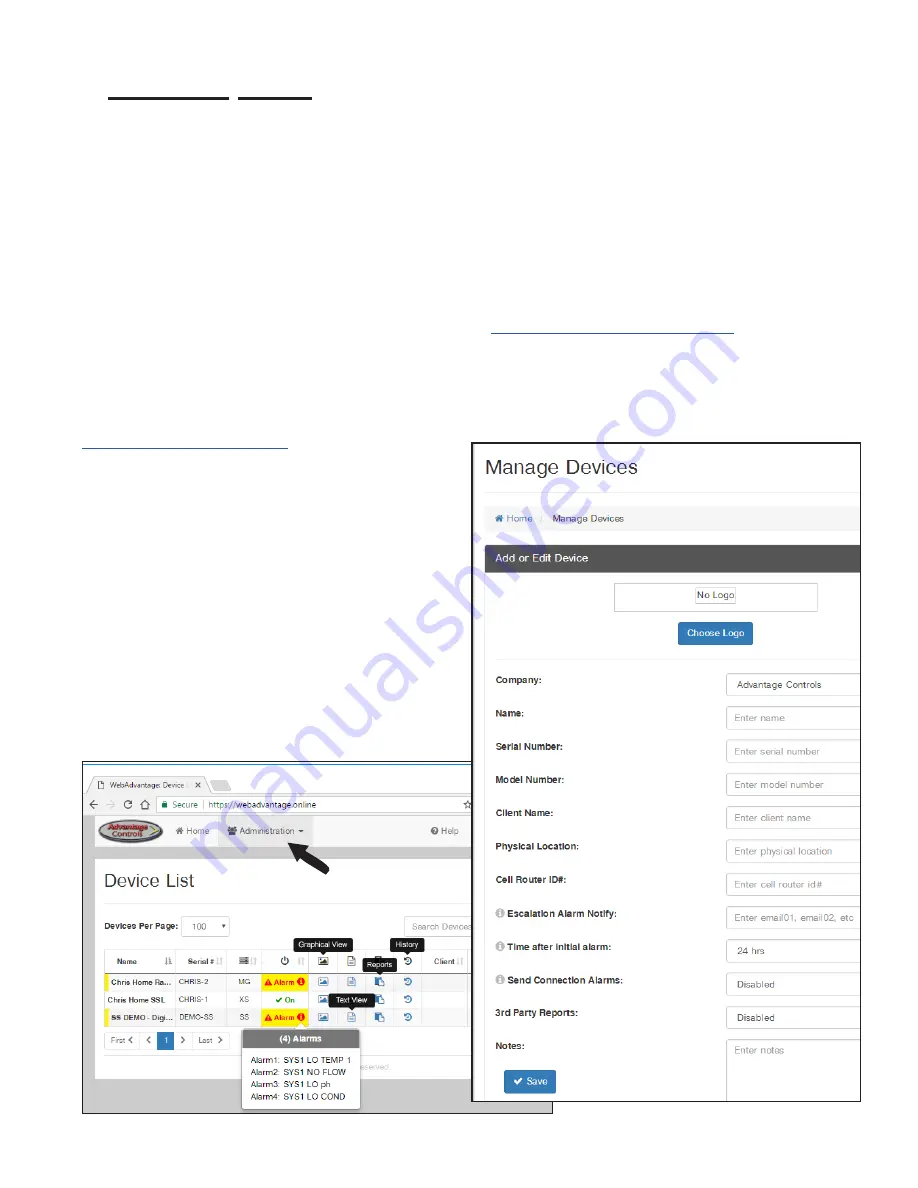
Step 1:

  Access the WebAdvantage page at 

https://webadvantage.online

.

Note: 

Only company administrators can add, edit, 

remove or modify devices, user accounts, history 

reports.  User account permissions only allow for 

viewing of devices. 


Step 2:

  Choose 

Administration

 at top of page.  

Step 3:

  Then choose 

Manage Devices

.  

Step 4:

  Enter the device’s 

Name

 and 

Serial 

Number

.  The remaining fields are optional.  

Click 

SAVE

 to submit.

Admins Only

: Add Device and Assign USER ID

Setting Up / Accessing a Device

Note:  Please allow up to 24 hrs for processing before 

controller shows in device list.

WebAdvantage support can be reached at 

918-686-6211 or via email at 

[email protected]

.

Содержание MegaTrom XSi

Страница 1: ...Instructions Read all warnings and instructions in this manual Save all instructions Advantage Controls 4700 Harold Abitz Dr Muskogee OK 74403 Phone 800 743 7431 Fax 888 686 6212 www advantagecontrols com support advantagecontrols com 09 2021 C US ...

Страница 2: ...enerates and uses radio frequency energy and if not installed and used properly that is in strict accordance with the manufacturer s instruction may cause interference to radio communications It has been type tested and found to comply with the limits for a class A computing device pursuant to subpart J of part 15 of FCC Rules which are designed to provide reasonable protection against such interf...

Страница 3: ...nstead of standard comm card H21 Communications card with BACnet via ethernet instead of standard comm card L 5 additional digital alarm inputs N4 4 4 20mA isolated inputs N8 8 4 20mA isolated inputs O4 is not available with the N8 option O4 4 4 20mA isolated outputs W4 4 totalizing flow meter inputs with volume tracking and alarming Y ETL agency listing Z Black cover instead of clear Model number...

Страница 4: ...lts the ground should be a true earth ground not shared Any attempt to bypass the grounding will compromise the safety of users and property 6 The electrical installation of the controller must be performed by trained personnel only and conform to all applicable National State and Local codes 7 Operation of this product in a manner not specified by the manufacturer may result in damage to equipmen...

Страница 5: ...E FUSE FUSE FUSE FUSE FUSE 2 1 10 9 NEU GND N O N C NEU GND N O N C NEU GND N O N C NEU GND N O N C Relay 1 Relay 2 Relay 3 Relay 4 Relay 5 R1 R2 R3 R4 R5 Incoming Power Fuse 15 amp H N G Incoming Power Relay Fuses are 3 amp Relays are shown configured for powered outputs Change jumpers to these configurations for dry contact Relays 1 3 Relays 4 5 Relay Card Rev N R1 R2 R3 R5 MegaTron relay card r...

Страница 6: ...ed configuration 4 20mA Input Card Wiring The 4 20mA input card requires that the external device sending the 4 20mA input signal s supply the power for the loop The external power source must not exceed 24 volts DC IN1 V V V V V V VEXT VEXT 01 01 02 02 03 03 04 04 ISO LED ISO ISO ISO IN1 IN2 IN2 IN3 IN3 IN4 IN4 J5 J4 mA Outputs are supplied as non isolated as shown For isolated outputs J4 and J5 ...

Страница 7: ...m initializes into RUN mode Press this key to put the controller in SET UP Mode and see HOME menu page ENTER Used to log a changed value into program HOME Used to go back to the HOME menu page CANCEL Used to cancel a pop up screen if no change is desired HELP Used to access help screens BACK Used to go back to last menu screen viewed or clear values keyed in that are not wanted The bottom right bo...

Страница 8: ...d through the sub menus to reach a point at which a value or selection is made a Pop up window will appear prompting you to enter a desired value or selection NOTE When entering new numeric values enter all available digits characters 1 Home Menu From the HOME menu select the desired menu The menu name explains what parameters can be programmed in the menu SET POINTS Setting control set points for...

Страница 9: ...ALARM What reading generates a Low alarm LIMIT TIMER What amount of continuous control will generate a time alarm notice The relay is locked out by this alarm DISABLER One of the digital inputs can be selected to prevent alarming Note Each alarm value can also be set up to be displayed or not on the front screen as well as remotely notified or not if connected to the Web Advantage server 2 2 Aux I...

Страница 10: ...m 0 4095 with 800 equal to 0 mA output and 4030 equal to 20 mA This number range of 0 4095 is the raw digital to analog D A values and is strictly used for a reference The D Anumbers you get will vary based on your installation conditions While in the High or Low calibration pop up screen use the up and down arrows to change the output value being read with the volt meter Adjust the High value for...

Страница 11: ... calibration of the displayed value FACTORY DEFAULT If the 20mA or 4mA calibration has been incorrectly set not at 4 or 20 this will reset the settings back to a factory value for 4 and 20 4 Customize This menu allows the user to define the on screen name of the unit plus the name of each system and relay The user can also setup the Notepad for each system and 4 20mA Input s name and unit of measu...

Страница 12: ...en SCREENS SHOWN Pick if the mA input Aux Flow screens are scrolled CYCLE TIME The amount of time between screen scrolls 5 Alarms ALARMS Shows any current alarms 6 Date and Time Set Up DATE AND TIME For setting the date time day and week on the controller 7 Configure Provides access to menus to set up passwords relay activation temp scale display contrast flow switch inputs history time stamps fac...

Страница 13: ...n for the max amount it does not let the relay come on anymore that day A 24 hour clock is used for the day with midnight being the start of the day The Delay setting is the amount of time a control function must come on before the relay will react and activate This is to prevent a relay from chattering on off if a reading is bouncing around the set point or alarm 7 3 History This menu is used to ...

Страница 14: ...T_H_WiFi pdf Note Some choices may not be available if DHCP or WIFI are disabled in previous NETWORK menu 7 8 System Information System information will identify the version of firmware installed in the controller along with the controller s serial number 8 History The onboard history allows for viewing the history of the mA readings relay activations key pad activity calibrations flow meter hourl...

Страница 15: ...Si controllers with W option may have 1 to 4 auxiliary flowmeter inputs These additional inputs are for tracking various flow meter devices additional water meters or flowmeters in a metering pump s discharge tubing They can also be linked to a system s water meter input for additional tracking and alarm capabilities including bleed flow no flow exceeding too much flow in a 12 or 24 hour period Un...

Страница 16: ...er will give an alarm if it does not receive a contact or pulse from the aux meter within the amount of time defined or if it gets a contact when the relay is not on RELAY LINK The relay link informs the particular aux meter input is relevant to the control function that the selected relay is being driven by For example if the aux flow meter is a metering pump s FloTracker then it should be linked...

Страница 17: ... manually forced ON for a single event from 0 99 minutes When the event is over the relay goes back to its normal automatic control In the STATUS view the accumulated ON time is shown along with the main activator custom name and current status ON Relay on by relay activators OFF Relay off by normal logic OFF T Relay off for daily max OFF D Relay off for relay disabler ON A Relay activated by acti...

Страница 18: ...rs for processing Setting Up a USER ID Before you can view a device a USER ID must be setup Note If you already have a USER ID and are just adding a new device skip to step 4 Step 1 Visit https webadvantage online or access the registration form with the QR code below Step 2 Choose Create Account at the bottom of the login screen Step 3 After completing form click SAVE to create ID Note The email ...

Страница 19: ...Note Only company administrators can add edit remove or modify devices user accounts history reports User account permissions only allow for viewing of devices Step 2 Choose Administration at top of page Step 3 Then choose Manage Devices Step 4 Enter the device s Name and Serial Number The remaining fields are optional Click SAVE to submit Admins Only Add Device and Assign USER ID Setting Up Acces...

Страница 20: ...istory USB by using the Arrow buttons Then press ENTER XS Controller 3 ALARMS RELAYS Friday February 6 2015 15 50 47 Wk1 SYS1 Towers 1 4 COND 0 uS cm pH 3 2 ORP 548 mV TEMP1 68 F WM1 0 0 WM2 0 0 FLOW ON DR USB DRIVE DETECTED History USB PRESS UP DOWN KEYS TO CHANGE PRESS ENTER TO ACCEPT Note Status will be displayed on the screen to show the percent completed of each log record type Once the log i...

Страница 21: ...graphing and multiple user internet access Contact Advantage Controls or support advantagecontrols com with your unit s serial number to learn more After an XS is set up for cloud storage follow these steps 1 Login to the secure web server https webadvantage online 2 Locate the controller you have data for and click Reports 3 Click History Upload on the left 4 Click Choose File and select the file...

Страница 22: ...ER HOME 3 4 5 2 1 8 9 0 7 6 SET UP RUN CANCEL HELP BACK ENTER HOME Step 1 With the controller powered up plug the USB drive into the XS USB port The USB DRIVE DETECTED pop up window will appear Select Config USB Config to USB by using the Arrow buttons Then press ENTER XS Controller 3 ALARMS RELAYS Friday February 6 2015 15 50 47 Wk1 SYS1 Towers 1 4 COND 0 uS cm pH 3 2 ORP 548 mV TEMP1 68 F WM1 0 ...

Страница 23: ...rt proven defective in material or workmanship upon manufacturer s examination Removal and installation costs are not included under this warranty Manufacturer s liability shall never exceed the selling price of equipment or part in question Advantage disclaims all liability for damage by its products caused by improper installation maintenance use or attempts to operate products beyond their inte...

Страница 24: ...ment needs Cooling Tower Controllers Boiler Blow Down Controllers Blow Down Valve Packages Solenoid Valves Water Meters Chemical Metering Pumps Corrosion Coupon Racks Chemical Solution Tanks Solid Feed Systems Feed Timers Filter Equipment Glycol Feed Systems Pre Fabricated Systems Get the Advantage 5 4 3 2 1 ENTER HELP 5 4 3 CHANGE RUN SET UP 0 9 8 2 1 7 6 HOME BACK ...

Отзывы: