background image


15 

2.2 

Installing the Enclosure 


The panel weight is heavy when the batteries are installed. Use the appropriate fixing 
hardware to secure the panel to the wall. Observe recommended lifting practices to guard 
against spinal injury. See table below for maximum weights. 


Enclosure  

Weight 

Maximum Battery 

Overall Maximum Weight 


/S (Small) 

6Kg 

7Ah 2.5Kg 

11Kg 


/M (Medium) 

8Kg 

12Ah 3.9Kg 

16Kg 


/L (Large) 

10Kg 

18Ah 5.7Kg 

22Kg 


/D (Large/Deep) 

12Kg 

45Ah 15.5Kg 

43Kg 


/E (Extended) 

18/20Kg 

45Ah 15.5Kg 

65Kg 

2.2.1  Opening the Enclosure Cover 

The enclosure covers are provided with a key-lock assembly for securing the hinged door to the back box. Insert 
and turn the key anti-clockwise to open the enclosure. 

2.2.2  Removing the Chassis 

It is recommended that the chassis be removed before fitting the panel to the wall. To remove the chassis: 

Disconnect the earth cable connecting the chassis to the spade terminal on the rear enclosure. 

Unplug the 3-way connector feeding the AC supply to the Base Card.  

Disconnect the ribbon cable connecting the display to the base card at the display. 

Loosen the two screws holding the chassis to the back box. There is no need to remove these screws fully 

– the 

chassis plate has keyhole style mounting holes. Carefully remove the chassis from the rear enclosure and place 
in a safe place to prevent accidental damage. 


Do not lift the chassis by holding onto any of the printed circuit cards. Hold the chassis by the 
metal plate only. 

2.2.3  Mounting the Enclosure 

Firstly, remove the required knockouts for the installation wiring. There are sufficient knockouts on the top of the 
enclosure for all installation wiring. In addition, there are knockouts at the top of the back wall, if required, for 
rear entry cabling. 

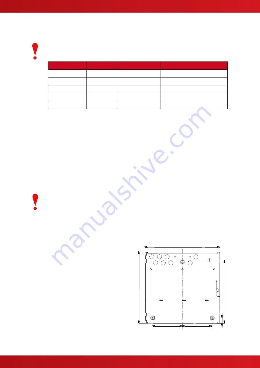
The enclosure is provided with three fixing points.  

The diagrams opposite and below show the 
positions of the three holes and dimensions of each 
enclosure. Use all three positions to ensure the 
panel is held securely to the wall. 

Drill the required holes in the supporting wall using a 
drill bit diameter 7.0 mm and plug with a suitable 
40mm or longer expansion plugs. Affix the panel to 
the wall with M5 screws or No.10 screws. Use 
appropriate fixings to support the weight including 
the batteries. 

Ensure that there is sufficient space to allow the 
door to be opened when the panel is mounted.  

Finally, use a brush to remove any dust or swarf 
from inside the enclosure.  


340 

34

0


29

9


135 

135 

26


(/S) Enclosure Size and Fixing Point Dimensions 

www.acornfiresecurity.com

www.acornfiresecurity.com

Содержание MxPro5

Страница 1: ...Fire Alarm Panels Product Manual The operation and functions described in this manual are available from Software Version 5000 050 04 onwards www acornfiresecurity com www acornfiresecurity com ...

Страница 2: ...h Efficiency Off Line Switched Mode 2x On board 24V DC 5A High Efficiency Off Line Switched Mode Output Voltage1 18 0V 28 0V 18 0V 28 0V 18 0V 28 0V 18 0V 28 0V Ripple Vpkpk 1 0V 1 0V 1 0V 1 0V Max Battery Ohms 1 6Ω 0 1 Ω 0 8Ω 0 1 Ω 0 8Ω 0 1 Ω 0 8Ω 0 1 Ω Imax a Imax b 2 1 6A 3 0A 2 6A 5 0A 2 6A 5 0A 2 6A 5 0A per chassis Number of Fire Zones 200 max 2000 when networked 200 max across 2 loops 2000 ...

Страница 3: ...L BUS MODULES 20 2 4 1 Routing Interface Card Plug In 20 2 4 2 2 Way Relay Card Plug In 21 2 4 3 Network Card 21 2 4 4 Peripheral Module Chassis Mounting 22 2 4 5 VdS Interface Module Chassis Mounting 23 2 4 5 1 Option Relay Card 23 2 4 5 2 Optional Redundant Ring Controller 23 2 5 WIRING INSTALLATION 24 2 5 1 AC Mains Wiring 24 2 5 1 1 Cable Gland 24 2 5 2 Battery Installation 25 2 5 2 1 Small En...

Страница 4: ... Panel finds Devices Missing 46 3 3 3 3 Procedure if the Panel finds Devices Added 46 3 3 3 4 Procedure if the Panel finds Devices Changed 47 3 3 4 Loop Calibrate 47 3 3 5 Loop History 47 3 3 6 Loop Meter 48 3 3 7 Loop Scope 48 3 3 8 Zones 49 3 3 9 Exit 49 3 3 10 Disable 49 3 3 11 Enable 49 3 3 12 View Options 50 3 3 13 Passwords 50 3 3 14 Time and Date 50 3 3 15 PC Config 50 3 3 16 EN54 13 51 3 3...

Страница 5: ...NDIX 2 RECOMMENDED FIRE RATED CABLES 64 5 2 1 Detector Loop Lengths Apollo Hochiki and AV 64 5 2 2 Sounder Circuit Lengths 65 5 2 3 Fire Fault Routing Circuit Lengths 65 5 2 4 Network Cables 65 5 3 APPENDIX 3 BATTERY STANDBY CALCULATION CHART 66 5 4 APPENDIX 4 CAUSE AND EFFECT PROGRAMMING EXAMPLE 67 5 4 1 Introduction 67 5 4 2 Output Groups 67 5 4 3 Styles 67 5 4 4 Output Group Programming 68 5 5 ...

Страница 6: ...puts Dependency on more than one alarm signal Fault Signals from Points Disablement of Points Alarm Counter Test Condition Standardised Input Output EN54 4 1997 A1 2002 A2 2006 Power supply equipment for fire detection and fire alarm systems for buildings Mx 5100 Mx 5200 Mx 5400 MX 5800 Mx 5100V Mx 5200V Mx 5400V MX 5800V Mx 5100N Mx 5200N Mx 5400N MX 5800N In addition the products comply with the...

Страница 7: ...larm Control Panels This manual provides generic programming and installation information Refer to the appropriate protocol application note for further and specific information for each protocol Refer to the User Manual Document No 680 166 for details of how to operate the panel All panel models are available in a range of enclosure sizes and with a range of alternative optional features 1 3 1 50...

Страница 8: ...uts Co incidence Detection Alarm Counter Fault Signals from Points Output to Fault Routing Equipment Disablement of Points Test Condition Standardised I O 7 8 7 9 7 10 7 11 7 12 Type B Type C 7 13 8 3 8 9 9 5 10 11 P S E Functions EN54 4 Clause Operation from a main power supply Operation from a standby battery Monitor and Charge the Standby Battery Recognise and Notify Supply Faults 5 1 5 2 5 3 5...

Страница 9: ...ce Requires installation of a routing interface card Refer to Sections 2 4 1 2 5 12 3 3 20 and 3 3 21 for further information Section 7 11 Delays to Outputs The C I E has provision for Output and Investigation Delays Refer to Sections 3 3 20 3 3 21 for further information Section 7 12 Coincidence Detection The C I E has provision for Coincidence Detection Refer to Section 3 3 20 for further inform...

Страница 10: ...1 6 Installation Approvals 1 6 1 Fire System Installations The panel must be installed and configured for operation in accordance with these instructions and the applicable code of practice or national standard regulations for fire systems installation for example BS5839 1 2002 appropriate to the country and location of the installation 1 6 2 Wiring Regulations The panel and system must be install...

Страница 11: ... for eight key switches or four key switches and a printer Option for a 50 Zone LED card WARNING HIGH VOLTAGE INSIDE DO NOT REMOVE COVER No Serviceable Parts Inside Display Loop Driver Base Card Chassis Door Back box Hinge Pin Display Cable AC Input Optional Zone LED Card Optional Key Switches Door Lock Ratings Label L Enclosure comprises Back Box Base Card with 1x Loop Driver mounted onto a Chass...

Страница 12: ... LED Card Optional Key Switches Door Lock Ratings Label L D Enclosures comprises Back Box Base Card with 2x Loop Drivers mounted onto a Chassis Plate Door with Display Card mounted onto a fascia plate Key Lock Option for eight key switches or four key switches and a printer Option for two 50 Zone LED cards The deep D enclosure arrangement is identical WARNING HIGH VOLTAGE INSIDE DO NOT REMOVE COVE...

Страница 13: ...r The MX 5800 consists of two independent systems comprising of 4 LP Base Cards and Display Cards only one display is normally visible and each system capable of supporting 512 detection devices Network cards are fitted as standard and wired internally Additional information on networking is detailed in document 680 502 For redundancy of indications and controls install an MX 5030 Remote Terminal ...

Страница 14: ...or Rittal or in Advanced MXM 510 XXU Rack enclosures Weight 6Kg For more information on the rack system and optional modules see document 680 195 MXM 510 16U Rack Enclosure 730 x 535 x 230 Steel 22Kg Glass Door IP55 Door Closed IP30 Door Open MXM 510 20U Rack Enclosure 910 x 535 x 230 Steel 25Kg Glass Door IP55 Door Closed IP30 Door Open 1U Blanking Plate Panel Module Blank Plates or Optional Modu...

Страница 15: ...crews fully the chassis plate has keyhole style mounting holes Carefully remove the chassis from the rear enclosure and place in a safe place to prevent accidental damage Do not lift the chassis by holding onto any of the printed circuit cards Hold the chassis by the metal plate only 2 2 3 Mounting the Enclosure Firstly remove the required knockouts for the installation wiring There are sufficient...

Страница 16: ...3 5 183 5 Knockouts x2 271 M Enclosure Size and Fixing Point Dimensions L Enclosure Size and knockouts top D Enclosure Size and knockouts top 447 472 431 26 183 5 183 5 Knockouts L x2 D x3 378 L D Enclosure Size and Fixing Point Dimensions www acornfiresecurity com www acornfiresecurity com ...

Страница 17: ... 2 2 4 Remounting the Chassis Carefully replace the chassis and fix into place using the two screws Reconnect the chassis earth cable to the spade terminal in the rear of the enclosure reconnect the display cable to the display card and then reconnect the AC supply lead to the Base Card www acornfiresecurity com www acornfiresecurity com ...

Страница 18: ...er information on cable types to be used Refer to specific sections on how to install AC Mains input and loop sounder relay and AUX outputs circuits WARNING HIGH VOLTAGE INSID DO NOT REMOVE COVER No Serviceable Parts Inside Loop Drivers 1 4 Base Card Chassis AC Input Loop 1 Loop 2 Loop 3 Loop 4 SND 3 4 SND 1 2 AUX PBUS SW I P RLY1 RLY2 LOOPS AUX PBUS SW I P RELAYS SOUNDERS AC INPUT AC Input Altern...

Страница 19: ...printed circuit boards Observe anti static precautions at all times when handling printed circuit boards A section of the Base Card identifying the locations for each loop driver is shown in the pictures below To install a loop driver operate the locking tabs of the card guides then gently guide the loop driver printed circuit card into the card guide slots and then push into place onto the connec...

Страница 20: ... Routing Interface Card Plug In Outputs to Routing Equipment Clauses 7 9 and 8 9 Output to Fire Protection Equipment Clause 7 10 The Routing Interface Card provides monitored outputs for connection to Fire Routing Equipment Item E and Fault Routing Equipment Item J or to Fire Protection Equipment Item G in accordance with EN54 2 The Mxp 532 Interface card is fitted to the base card using 1x M3 scr...

Страница 21: ...xp 503 STD or an Mxp 509 FT Network Card can be installed onto the base card The card is fitted to the base card using 1x M3 screw and 3x plastic pillars A metal pillar is pre fitted to the base card Refer to the diagram opposite All signals and power required for operation of the card are provided on the plug in connections Plug the ribbon cable into the connector as shown The screw fixing is ess...

Страница 22: ...rther information The screw fixing is essential for EMC Immunity protection WARNING HIGH VOLTAGE INSIDE DO NOT REMOVE COVER No Serviceable Parts Inside Mxp 034 Power and Data Route along edge of chassis and tie in place with tie wraps Base Card 2 LP shown Mounting Position on Chassis MXP 034 4 Way Sounder shown Isolate ALL sources of power before installing or removing printed circuit boards Obser...

Страница 23: ...er before installing or removing printed circuit boards 2 4 5 1 Option Relay Card An optional Mxp 508 8 Way Relay Card can be mounted on top of the interface card to provide additional relay output circuits Use the supplied pillars to secure the Interface card to the chassis using the lower 4 mounting holes Mount the relay card onto the pillars using the supplied M3 screws and connect the ribbon c...

Страница 24: ...ight corner only Keep the AC wiring away from the circuit boards and all other wiring FUSE Brown Green LIVE EARTH NEUTRAL Panel Wiring Blue 3 15A AC Mains terminations The fuse is rated as follows T 3 15A H 250V Replace with correct rating and specification only Must be earthed The panels must be connected to the supply earth through the power cable The mains input connector is shown in the diagra...

Страница 25: ... the negative terminal of battery 2 Connect the negative of battery 1 to the positive of battery 2 using the supplied link cable Ensure that the battery terminals do not short out against any part of the enclosure circuit board or chassis plate 1 2 RED BLACK Link Cable Do not make the final battery connections until the installation wiring is completed and the system is to be powered up Always con...

Страница 26: ...l WARNING HIGH VOLTAGE INSIDE DO NOT REMOVE COVER No Serviceable Parts Inside 2 5 2 3 Large Enclosure The diagrams opposite show the recommended location and orientation for 7Ah 17AH batteries within the panel WARNING HIGH VOLTAGE INSID DO NOT REMOVE COVER No Serviceable Parts Inside www acornfiresecurity com www acornfiresecurity com ...

Страница 27: ...agrams opposite show the recommended location and orientation for 7Ah 38AH 45AH batteries within the panel WARNING HIGH VOLTAGE INSID DO NOT REMOVE COVER No Serviceable Parts Inside www acornfiresecurity com www acornfiresecurity com ...

Страница 28: ...Base Card Terminations Typical When screened cable is used it is vital to connect the screen drain wire to the chassis earth at the cable gland input earth stud in the panel Always ensure that all segments of the cable loop have continuity of the screen and take care to ensure that the screen is not exposed to any other earth point e g metalwork cable trays junction boxes etc The Loop Driver Circu...

Страница 29: ... have continuity of the screen and take care to ensure that the screen is not exposed to any other earth point e g metalwork cable trays junction boxes etc The sounder outputs support monitoring with an Active EOL device to ensure circuit integrity in accordance with the requirements of EN54 13 The sounder circuits can be configured for compliance with EN54 13 by programming and the use of an Acti...

Страница 30: ...irst panel to the IN socket on the next panel as follows SCN B A A B SCN IN OUT To Base Card OUT Screen B A Screen B A IN STD Up to 32 nodes The IN terminals on the first node and the OUT terminals on the last node are not used Connect an ELR 150Ω resistor between A and B on the terminal blocks of the unused sockets Maximum cable length overall length is 1500m using recommended cables FT Up to 200...

Страница 31: ...EN54 2 compliant 2 5 7 Auxiliary Supply Output The MxPro 5 Series are equipped with an auxiliary 24V DC 500mA power supply output This can be used for powering ancillary equipment and must only be used for powering localised internal equipment B A 0V 24V SW COM AUX SWITCH PBUS Base Card connections 2 5 8 Isolated Peripheral Bus Interface The isolated bus interface is used to connect local peripher...

Страница 32: ...et for a user text description The switch cable connector plugs into the display card connector as show opposite Switch Input Connector Optional Key Switches 87654321 Route the switch cables along the bottom of the fascia plate and fix with tie wraps to the return flange Slide in label Display Plate Arrangement Typical 2 5 10 RS232 Interface The Mx 5000 Series are equipped with an isolated RS232 I...

Страница 33: ...iven by another fire routing output located on a separate panel Routing Interface FIRE 1 FAULT FAILSAFE INPUT Output from another panel OUT IN OUT IN FSI OUT IN FIRE 2 470R 10K MONITORED INPUT CIRCUIT Typical Options 3K3 680R or 10K 470R Typical Arrangement 2 5 12 2 Fire Protection Routing The Interface monitors the wiring to and from the Fire Protection function i e Extinguishing panel A separate...

Страница 34: ... default If set to monitored EOL 10KΩ Active Resistance 470Ω 1 2 3 4 15 16 17 18 11 12 13 14 5 6 7 8 9 10 FAT FBF FSD ÜE AUSG S red ÜE RS232 To base card To relay card Learn Circuit Typical Arrangement IN OUT FUNCTION COMMENTS 1 OUT FAT DC POWER 24V 24V DC 0 5A Power limited 2 OUT FAT DC POWER 0V 3 IN OUT RS485 A Serial Communications 4 IN OUT RS485 B 5 OUT FSD DC POWER 24V 24V DC 0 5A Power limit...

Страница 35: ...nd connect specific types RS485 Connection RS232 Connection Note Units connected via RS232 must be wired in rigid conduit and located 3 metres from the panel FAT 1 2 3 4 FAT FBF RXD RXD UB1 UB1 RS485 Connect 150R EOL across RXD RXD at FAT FAT 1 2 3 4 FAT FBF RS232 21 20 19 TXD RXD GND UB1 UB1 RS232 FBF 1 2 3 4 FAT FBF V 27 V 26 RS485 RXD RXD Connect 150R EOL across RXD RXD at FBF FBF 1 2 3 4 FAT F...

Страница 36: ... 1 2 3 4 FAT FBF RS232 ADP N3S 0V TX RX TX RX 0V PANEL 1 PANEL n AUSG AUSG V 27 V 26 UB2 UB2 SIO2 SIO2 UB1 UB1 SIO1 SIO1 UB2 UB2 SIO2 SIO2 UB1 UB1 SIO1 SIO1 UB2 UB2 SIO2 SIO2 UB1 UB1 SIO1 SIO1 UB1 UB1 SIO1 SIO1 UB2 UB2 SIO2 SIO2 UB1 UB1 SIO1 SIO1 UB2 UB2 SIO2 SIO2 Both power 24V DC and data communications are distributed around the ring 2 5 13 3 FSD Key Deposit Box Connection The interface is comp...

Страница 37: ... system fault condition the fail safe input is automatically connected to the ÜE output The router should be provided with power from a separate power supply Router Coil 200 5000ohm 24V DC 11 12 13 14 ÜE ACK FIRE 0V 24V 15 16 17 18 AUSG S red ÜE 11 12 13 14 ÜE Connect the ÜE Output on another network node to the Fail Safe Input on the Interface card connected to the router Node 1 Node n 0V Connect...

Страница 38: ... Passwords If this number is lost it is not possible to enter commission mode functions Refer to section 5 1 for further formation Default 7654 3 1 2 Memory Lock The configuration memory may be protected against inadvertent change by means of a memory lock Before making any configuration data changes move the jumper strap to the OPEN position After all changes have been made move the jumper strap ...

Страница 39: ...quired character wait for 1 second and the character will be entered and the cursor will move to the next character in the text description Pressing another button will immediately enter the previous character and move the cursor on to the next character Use the buttons to move backwards or forwards along the line When the text description is as required press the button to confirm the change If t...

Страница 40: ...are reporting an alarm condition during test Disabled View Zones Inputs and Outputs that are disabled Inputs View the current state of Zones and Inputs Outputs View the current operational condition of all output circuits Log View the Event Log Panel View the software of all installed components and the operational state voltage current loading of the panel I O hardware Network View Network Diagno...

Страница 41: ...0 Press the buttons to scroll through the list of loops available and then press the button to select the loop required Note For the 5100 and as there is only one possible circuit the display will immediately show a list of programming options as follows Loop 1 VIEW EDIT AUTO LEARN CALIBRATE HISTORY METER SCOPE 3 3 2 Loops View Edit The VIEW EDIT option shows a list of the devices connected to the...

Страница 42: ...1 32 Use the number keys to change the meldergruppe number assigned to the device 3 3 2 5 Device Text This parameter shows the 26 character location text assigned to this device For guidance on how to change the text refer to Section 3 1 4 3 3 2 6 Action This parameter shows the action that will be performed when this device indicates an active alarm condition For example Loop 1 Devices More Addre...

Страница 43: ...plication note for further information This parameter shows if the device sensitivity is set to its DEFAULT or CUSTOM settings For example Loop 1 Devices More Address Sensitivity 001 0 DEFAULT 002 0 DEFAULT 003 0 CUSTOM 004 0 DEFAULT Press the button to change the sensitivity assigned to an input device When selected a new screen displays the sensitivity settings assigned For example with an Apoll...

Страница 44: ...y 5s Min Value 8 SAM SSM In the above example the panel is using special sensitivity mode 5 and time clock number 2 Enter 0 in the SSM Clock field to cancel Special Sensitivity Mode A number must be entered in the SSM Clock field to select the appropriate SSM number and time clock To view the time clock settings highlight the SSM Clock field and press the button For example Time Clock 2 DAY ON OFF...

Страница 45: ...luminate the detector LED and individual outputs sounders and relays can be tested to check output connections and operation While the address field is highlighted press the buttons to scroll through the list of devices to the desired device or key in the address and then press the button Loop 1 Devices More Address State Type Value 005 1 Normal SOUNDER 006 0 Normal MULTI SENSOR 16 006 1 Normal RE...

Страница 46: ...ess is suspended and the display shows a pop up window with options For example KEEP THIS DEVICE DELETE THIS DEVICE KEEP ALL MISSING DELETE ALL MISSING Address 002 DEVICE MISSING If the missing device is kept or all missing devices are kept the panel remembers the programming for these devices The panel will report a fault condition until such time as the missing devices are reconnected If the mis...

Страница 47: ...ACCEPT ALL NEW DEVICES REJECT ALL NEW DEVICES Address 002 TYPE CHANGE This situation could arise for example if a heat detector has been installed in place of an optical smoke detector If the new device type is accepted or all new device types are accepted the panel will configure the memory to register these devices All data will be configured to initial settings for sensitivity threshold changes...

Страница 48: ...me that the device was last re enabled Created The date and time that the device was either auto learnt at the panel or added to the device list from a PC configuration 3 3 6 Loop Meter Displays loop output and input voltages and loop loading A diagnostic display with automatic scanning of the loop to find devices with minimum and maximum communication pulse heights is available 3 3 7 Loop Scope T...

Страница 49: ...xample Commission Menu 1 Please Enter Your Password Next Menu If the password is incorrect this will be indicated or if the password is not entered within 5 seconds the display will revert to the Commission Level Menu and level 2 will not be entered After commissioning the panel must always be returned to level 2 or level 1 to give normal fire coverage 3 3 10 Disable This function is the same as U...

Страница 50: ...ction allows the time and date in the panel to be changed On entry to the function the display shows the current time and date with confirmation of the day of the week on the bottom line For example SET TIME DATE TIME 15 28 DATE 15 01 09 THU 15 JAN 2009 To change the settings use the buttons to highlight the required option Directly enter the new time or date using the number buttons As soon as a ...

Страница 51: ... user manual 3 3 17 Setup The Setup Options Menu enables the configuration of panel generic operating parameters When the option is selected the display shows a list of the available parameters For example Setup THIS NETWORK NODE 0 NEXT NETWORK NODE 0 PANEL ZONE 100 SERVICE NUMBER 01234 567890 Use the buttons to scroll through the list of options The following will then be shown Setup SERVICE DUE ...

Страница 52: ...o what level is stored in the Event Log There are three options STANDARD the normal operating mode logging fire alarm fault and warning conditions as they occur STANDARD an extended version of the standard operating mode where the removal of fault and warning conditions are also logged DIAGNOSTIC a full diagnostic trace of all conditions with greater depth to aid diagnosis of fault conditions To c...

Страница 53: ...e configuration data A note of this number can be taken and then checked on the next service visit to see if any changes have been made to the configuration data Setup CONFIG DATA APOLLO More To change the protocol press the button A pop up window is shown with the following options KEEP PROTOCOL CHANGE LOOP PROTOCOL Use the buttons to select the required options and press the button to confirm th...

Страница 54: ...Option shows a list of the internal panel circuits and provides a means to change their default configuration settings Only use this menu if changes are to be made to the default settings for the panel s internal circuits Use the VIEW PANEL Menu Option to view the state and operating condition of each circuit The display shows for example More Address State Type Value 001 0 Normal VOLTAGE 5 6V 001...

Страница 55: ...pply but the fault condition is only reported after the delay time default 10s has elapsed SENSITIVITY ADJUST MODE MONITOR Alarm Pre Alarm Delay 10s Min Value 372 SAM SSM To delay the reporting of an AC Supply Loss change the Delay setting 12 12 For compliance with EN54 4 the loss of the AC Mains supply should not be delayed more than 30 minutes 1800s www acornfiresecurity com www acornfiresecurit...

Страница 56: ...en enter the number of the output group required using the number buttons The display always shows the Output Group is shown in the top left corner Press the buttons to scroll through the list of zones Press the buttons to select the fields for a particular zone Press the button to select a particular field option to change its setting 3 3 20 1 Default Output Settings On initial installation or af...

Страница 57: ...ypes in which case a combination of input events will result in an output action If there is a combination of input events the CAUSE display above shows this extended programming by adding a to the text For example Zone 2 above shows that the basic event is ANY FIRE other criteria Press the Esc button to return to the previous display The definition for each cause is as follows Cause Definition Fi...

Страница 58: ...can be programmed to turn on differently such as ON The wait time can be set in intervals of 1 second up to a maximum of 250 seconds Press the button to step on to the wait field and change the setting using number entry 3 3 20 7 Copying Output Settings to Multiple Zones To save time in the entry of similar Output Group Settings for each zone it is possible to copy information programmed for a par...

Страница 59: ...mmed to turn on all outputs immediately 3 3 22 Test This function is the same as User Level 2 function refer to User Manual for further information The following functions can be tested Zones Inputs Display Buzzer Printer Outputs 3 3 23 LED Indications This option is not provided from Software Version 050 04 The operation of all MXP 513 XXX LED Indicator Cards MUST be configured using the PC Tool ...

Страница 60: ... addressed check the event log in the panel and take the necessary remedial actions b Visually inspect the panel for any moisture ingress or other deterioration check all battery connections and test check the alarm fault and other functions of the panel operation c Ascertain if any building or structural alterations have been carried out that would affect the placement location of call points or ...

Страница 61: ...to battery manufacturer for further information Manufacturer Part Numbers YUASA POWERSONIC 4AH NP4 12 5AH PS 1250 7AH NP7 12 7AH PS 1270 12AH NP12 12 12AH PS 12110 17AH NP18 12 18AH PS 12170 24AH NP24 12B 26AH PS 12260 38AH NP24 38 38AH PS 12380 45AH PS 12450 STOP For optimum performance and charge retention Yuasa recommend that batteries are top charged prior to installation For batteries up to 6...

Страница 62: ...ription MXS 501 1 LP Base Card only AP HO MXS 501V 1 LP Base Card only AV MXS 501N 1 LP Base Card only NITTAN MXS 502 2 LP Base Card only AP HO MXS 502V 2 LP Base Card only AV MXS 502N 2 LP Base Card only NITTAN MXS 503 4 LP Base Card only AP HO MXS 503V 4 LP Base Card only AV MXS 503N 4 LP Base Card only NITTAN MXS 504 Display Card Common to all panel types For all other items please refer to the...

Страница 63: ...or the password As soon as the Password Invalid message is shown press the 0 button and the display will show a decryption key Make a note of the first part of this number For example Level 2 Menu Please Enter Your Password 214728378 Customer Support will provide a temporary permit number that you can enter when prompted for the Level 3 password As soon as access has been regained to the Level 3 P...

Страница 64: ...d AV 16 With the above cables loops can be up to 2Km in length However care must be taken when designing the system to take into account the maximum loop loading The voltage drop load current x cable resistance over the cable always needs to be taken into account to ensure the devices receive an adequate supply voltage The following table gives recommendations for a loop It may be possible to exte...

Страница 65: ...5mm 2 is 0 024Ω metre Cable Resistance RCABLE for 2 5mm 2 is 0 015Ω metre Insulation Resistance Core Core and Core Screen 2M Ω 5 2 3 Fire Fault Routing Circuit Lengths The voltage drop on each transmission circuit should be calculated to ensure that the minimum voltage at the end of the circuit exceeds the minimum required by the relay coil at the minimum circuit output voltage Typically relays wi...

Страница 66: ...nce the loop voltage is different to other protocols 18 Use the detector manufacturers technical information to calculate the load on the loop for both the quiescent condition and fire alarm condition for all loop devices By default a maximum of 5 detector call point LED indicators will be turned on in a fire alarm condition This number can be changed via the PC Programming Tool 19 The calculated ...

Страница 67: ...f Floor 6 Output Group 6 Assign All Sounders of Floor 7 Output Group 7 Assign All Sounders of Floor 8 Output Group 8 Refer to Section 3 3 2 8 for how to assign the output group to a loop output device Refer to Section 3 3 20 1 for how to assign the output group to an internal panel circuit 5 4 3 Styles In the example there are two ways in which the sounders should ring These two operational charac...

Страница 68: ... 02 30s Pulse 120s 24 ANY FIRE 02 30s Pulse 120s STYLE 02 MODE Wait MODE On On On More Output Group 7 Sounders on Floor 7 Output Group 7 3 9 Mem used ZONE CAUSE STYLE Delay MODE Wait 22 ANY FIRE 00 On 23 ANY FIRE 00 On 24 ANY FIRE 00 On STYLE 00 MODE Wait MODE More Output Group 8 Sounders on Floor 8 Output Group 8 3 9 Mem used ZONE CAUSE STYLE Delay MODE Wait 22 ANY FIRE 02 30s Pulse 120s 23 ANY F...

Страница 69: ...tion with detector LED driven base sounders Also details limitations 680 085 Software Upgrades Application Note Explains how to upgrade the software in the Graphics Display Card and Fault Tolerant Network Card Refer to 680 030 for general panel software flash programming information and guidance 680 088 Cables for Fire Systems Application Note Gives further information on the cables than can be us...

Страница 70: ...ng EN54 2 1997 Clauses 7 9 8 9 Network If provided then at least two fire and fault routing interfaces or a fail safe redundant connection shall be provided These should be programmed to report all fire and all fault conditions See 2 5 13 and 2 5 12 for further information 5 6 2 Network Wiring Where the installation design and codes of practice deem the network connections to be a Critical Signal ...

Страница 71: ...0 10 Max of Output Groups 200 200 200 20026 200 200 200 Max of Output Group Lines 1150 1150 1150 115026 250 250 250 Requires PC CONFIG to define more than one line per Output Group Max of Passwords 12 12 12 12 12 12 12 Max of Sectors Available 100 100 100 100 100 100 100 PC CONFIG Only Max of Input Events 250 250 250 25026 100 100 250 PC CONFIG Only Max of Logic Blocks 100 100 100 10026 50 50 50 P...

Страница 72: ...72 This page is intentionally left blank www acornfiresecurity com www acornfiresecurity com ...

Страница 73: ...73 USER NOTES www acornfiresecurity com www acornfiresecurity com ...

Страница 74: ...74 www acornfiresecurity com www acornfiresecurity com ...

Отзывы:

Похожие инструкции для MxPro5