Epoch-M1C RF Repeater
User Manual V1.1
Advanced RF Technologies, Inc. Proprietary Document
Page 6 of 38
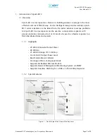
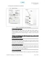
1. Server Antenna Port
One end of the coax cable will connect to the “Server Antenna Port” of
Epoch-M1C while the other end of the cable will connect to the server
antenna which is pointing towards the intended coverage area.
2. Power LED
The Power LED will be lit Green if the power is turned on and will be not
lit if the power is turned off.
3. Wireless Modem Access
You can manually place or take off the wireless modem.
4. Donor Antenna Port
One end of the coax cable will connect to the “Donor Antenna Port” of
Epoch-M1C while the other end of the cable will connect to the donor
antenna which is pointing towards the BTS.
5. VFD Display
In this display, you are able to view the repeater vitals in each link (e.g.
RSS, Gain, Output Power & Alarms).
6. Alarm LED
If there is an alarm, the Alarm LED will be lit Red. If there is no alarm the
LED will not be lit.
7. VFD
VFD stands for “Vacuum Fluorescent Display.”
** Please refer to Appendix B for more detailed information on how the
VFD button operates.
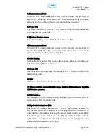
8. USB Interface
For management and troubleshooting purposes, you can connect your PC
to the Epoch-M1C via a USB cable.
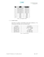
9. Dry Contact Interface (AAI)
AAI stands for Auxiliary Alarm Input. It acts as the interface between the
two devices (Epoch-M1C & DAS or third-party repeater) so that it can
pass alarming information from the third-party device to the Epoch-M1C.
The following table illustrates the PIN assignment which can be
customized according to the third-party device so that proper alarming
parameters are passed to Epoch-M1C.

