


March 1, 2002 Page F5
DC Power Supply and Inserter
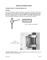
Inside the building, route the RG-6 from the building entrance point to the modem location.
Attach an F connector and connect it to the “TO AMPLIFIER” or “TO ANTENNA” F female
connector on the power inserter. Depending on the version, the wall mounted DC power supply
may:
- be permanently connected to the
inserter as shown in Figure F4, left, or
- connect to the inserter with a small DC plug
and jack, or
- be an F connector lead to the “12 VDC IN”
connector on the power inserter. [In the F-
connector case, ARCi will supply a 12-inch F-
male-to-F-male cable to connect to the power
supply. The installer may choose to furnish a
longer cable based on the installation
specifics].
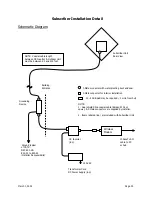
Modem (WMU)
Place the modem where it will be used and attach the short cable on the power inserter (labeled
“TO TV” or “TO MODEM” – see Figure F6) to the F connector on the rear of the modem. Connect
(the separate) modem wall mounted power supply (included with the modem) to the power
connector on the rear of the
modem. Plug both wall
mounted power supplies
into suitable AC power
sources – preferably a UPS
or surge protected power
strip. Connect a straight-
through 10BaseT LAN cable
between the RJ-45 jack on
the modem and the user
hub, router or personal
computer.
Figure F4
Power Inserter and
DC Power Supply
Figure F5
Power Inserter Detail
To Modem
To Antenna
Содержание AR1255
Страница 4: ...March 1 2002 Page A1 A Table of Contents ...
Страница 6: ...March 1 2002 Page B1 B Introduction C t t ...
Страница 9: ...March 1 2002 Page C1 C System Description ...
Страница 18: ...March 1 2002 Page D1 D Antenna and Frequency Planning ...
Страница 24: ...March 1 2002 Page E1 E Hub Installation Detail ...
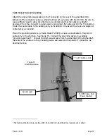
Страница 29: ...March 1 2002 Page E6 Figure E4 Hub Antenna and Cable Installation Cable Access ...
Страница 40: ...March 1 2002 Page F1 F Subscriber Inst l Details ...
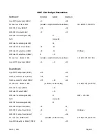
Страница 46: ...March 1 2002 Page G1 G Link Budget Parameters ...