


ACR350 Validator with QR Code Scanner
–
User Manual
Version 1.02
www.acs.com.hk
Page 26 of 61
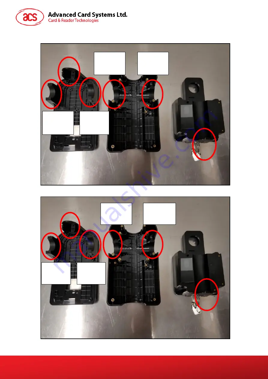
For
31/32mm pole
:
For
35mm pole
:
VT
Hole Cover
HT-D31/32
Rubber
Adapter
HT-D31/32
Rubber
Adapter
HB-D31/32
Rubber
Adapter
HB-D31/32
Rubber
Adapter
VT
Hole Cover
HT-D35
Rubber
Adapter
HT-D35
Rubber
Adapter
HB-D35
Rubber
Adapter
HB-D35
Rubber
Adapter
VT
Hole Cover
VT
Hole Cover


