background image


9  | 

P a g e

 - Ver. 1.1 - 09-22


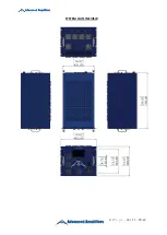
SYSTEM OUTLINE VIEW


Содержание AA-13G-500/1KWP

Страница 1: ...1 P a g e Ver 1 1 09 22 Instruction Manual Including Quick Start Guide Advanced Amplifiers Solid State RF Amplifier System AMP2103P LC AA 13G 500 1KWP 0 8 3 2 GHz 1000 Watt Pulse 500W CW 60 dB Min...

Страница 2: ...PECIFICATIONS 4 AVAILABLE SPECIAL OPTIONS 4 OPERATING INSTRUCTIONS GENERAL INFORMATION 5 INTRODUCTION 5 INCOMING INSPECTION 5 RF AC CABLE CONNECTION 5 RF TURN ON PROCEDURE 5 RF TURN OFF PROCEDURE 5 DE...

Страница 3: ...ecting the output load or other components The main power source to the equipment must have an uninterrupted safety ground that has sufficient size to the power cord REPAIR MAINTENANCE All repair or m...

Страница 4: ...nits with optional digital monitor and control for basic units 1 minute at rated Pout 3 Droop 1dB Typ 100usec overshoot droop 1dB Typ 560 sec ENVIRONMENTAL CHARACTERISTICS Parameter Specification Note...

Страница 5: ...rface and commands list is in the second part of the manual RF AC CABLE CONNECTION RF Input and Output connectors are outlined in the specifications table Use the standard AC cable that was supplied b...

Страница 6: ...or replacement of defective goods F O B factory of which Seller is modified in writing by Buyer within three 3 years following delivery thereof to Buyer and in no event will Seller be liable for incid...

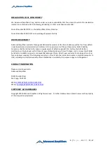
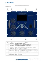
Страница 7: ...Control LCD Panel 3 FAULT LED System Fault LED Turn ON an LED when Over Temp Ext Shutdown 4 POWER LED Turn On a LED when Power Supply On 5 GATE CONTROL CW mode a TTL high of 3 3 5 0vdc is applied to a...

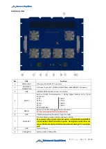
Страница 8: ...P7 N C P3 RX P8 N C P4 RX P9 N C P5 GND RS 422 5 DEBUG System Controller Debugging Female Connector Port access required factory authorization 6 USB USB Communication Connector Type A Female 7 ETHERN...

Страница 9: ...9 P a g e Ver 1 1 09 22 SYSTEM OUTLINE VIEW...

Отзывы: