2
Copyright © 2012 ADTRAN, Inc. All Rights Reserved.
Quick Start Guide, 61700416F1-13C, September 2012
3
M
OUNTING THE
AP
TO A
D
ROPPED
C
EILING
The NetVanta 160/161 AP is shipped with a metal ceiling
mounting kit to mount the AP on the ceiling tile separators of
standard dropped ceilings. The plastic mounting bracket can
be used to mount the AP to a drywall ceiling or ceiling
electrical box. Refer to
Mounting the AP to Drywall or
Electrical Box
for instructions. NetVanta APs should be
positioned for maximum throughput and range between other
APs and wireless client devices.
To mount the NetVanta 160/161 AP to a dropped ceiling:
1. For the NetVanta 161 only: Install the antennas (sold
separately) onto an appropriate antenna ports on the AP.
The antenna ports are labeled
2.4G 1
through
3
or
5G 1
through
3
.
2. Using the thumb screws only, carefully thread the antenna
onto the appropriate connector until it is secure. Repeat
Steps 1 and 2 with the each antenna.
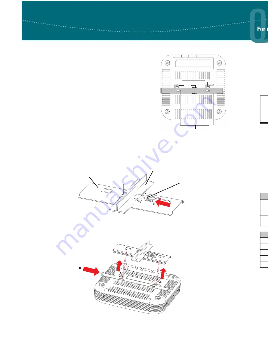
3. Lay the metal slider on the back of the AP in the orientation shown in the illustration above. Attach
the slider to the back of the AP using the two small screws provided. After the screws are tightened,
the slider should slide back and forth clicking into each position.
4. In a suitable location away from obstructions, slide the tabs on the metal ceiling bracket over one
edge of a ceiling tile separator.
5. Slide the moveable section into place and tighten the screw to secure it.
6. Position the AP so that the two tabs on the ceiling bracket locate in the slots in the AP (
A
). Push the
slider mounted on the AP across until it snaps, locking the AP to the bracket (
B
).
Screws
Metal Slider
Slots
Tab
Tab
Metal Slider
Screw (Shown from Above)
Moveable Section
Ceiling Tile Separator
Metal Ceiling Bracket
Tabs
S
UPPLYING
P
OWER TO THE
AP
The NetVanta 160/161 AP does not have a power switch. It is powered when connected to ADTRAN’s
Single Port Power over Ethernet (PoE) Injector (P/N 1700920F1) or an access controller (AC) that
supplies PoE based on the IEEE 802.3af standard. The NetVanta 160/161 can be powered by an
optional external DC power adapter (P/N 1700922F1) connected to an AC power source. The DC power
adapter automatically adjusts to any voltage between 100 and 240 VAC at 50 or 60 Hz. No voltage
range settings are required. The external DC power adapter is not automatically shipped with the
NetVanta 160/161 AP but can be requested from ADTRAN or your reseller.
C
ONNECTING TO THE
AP
Connect the NetVanta 160/161 AP to the Ethernet port of the AC or to an Ethernet port on a unit that can
be accessed by the AC. Connect the RJ-45 Ethernet connector on the AP's back panel (labeled
LAN
) to
your network using a CAT 5 Ethernet cable. When the AP and the AC are powered on, the AP's network
LED will light indicating a valid network connection.
The NetVanta 160/161 AP is managed by the AC over ADTRAN Wireless Control Protocol (AWCP)
using the Ethernet LAN port of the AP rather than the console port. Because the console port is only
necessary for purposes of debugging beyond the typical case, a typical user will have no need of
console access to the AP.
N
ET
V
ANTA
160/161 AP LED
S
LED indicators are located on the top of the NetVanta 160/161 AP unit. The following tabled list the
LEDs and their behaviors.
If the AP is used in a medical environment, it must use an IEC/EN 60601-1 compliant
power adapter.
Status LED
2.4G LED
5G LED
Description
Amber Solid
Off
Off
The unit is powering up.
Green Solid
Off
Off
The unit is initializing software and
acquiring an IP address.
Green Solid
Green Solid/
Flashing
Green Solid/
Flashing
The radios are activated and
passing traffic.
Network LED
Description
Off
No link is detected.
Amber Solid
A 10/100Base-T link detected with no activity.
Amber Flashing
A 10/100Base-T link detected with activity.
Green Solid
A 1000Base-T link detected with no activity.
Green Flashing
A 1000Base-T link detected with activity.


