


Chapter 6. Configuration
61202.029L2-1
ISU 128 User Manual
45
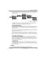
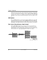
Data Format (Asynchronous)
A frame consists of a start bit, 7 or 8 data bits, 0 or 1 parity bit, and 1 to 2 stop
bits. The settings for
Data Bits
,
Parity Bits
, and
Stop Bits
are available as
shown in Figure 6-18.
Figure 6-18
Data Format Menu Tree
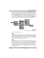
Transmit Clock (Synchronous Data Format)
Selecting the
Normal
option causes the ISU 128 to be the synchronous DTE in-
terface transmit timing source. Transmit data is timed from the transmit clock
provided by the ISU 128 on the DTE connector.
Normal clock
is the normal
mode of operation for the ISU 128.
With the
External
option selected, the ISU 128 slaves to an external transmit
timing source. The external clock is provided to the ISU 128 by the external
transmit clock signal at the DTE connector. This signal is echoed by the ISU
128 to the transmit clock signal on the DTE connector.
This option provides for situations where equipment connected to the ISU 128
DTE connector cannot slave to the ISU 128 provided clock. The ISU 128 uses
the U-interface as the frequency standard when it must provide a synchronous
receive or transmit clock. The externally provided clock must be of the same
average frequency as the clock that the ISU 128 would provide if internal clock
were selected. If this is not the case, then bit errors may occur.
3=CONFIG
1=Netw. options
2=DTE options
3=Protocol
4=Quick setup
5=Remote config
1=Bit Rate
2=Connector Type
3=RTS Options
4=CTS Options
5=CD Options
6=DTR Options
7=DSR Options
8=Flow Control
9=Data Format
1=Asynchronous
2=Synchronous
1=Data Bits
2=Parity Bits
3=Stop Bits
1=8 Data Bits
2=7 Data Bits
1=1 Stop bit
2=1.5 Stop bits
3=2 Stop bits
1=None
2=Odd
3=Even
Содержание ISU 128
Страница 11: ...Table of Contents vi ISU 128 User Manual 61202 029L2 1 ...
Страница 15: ...List of Tables xii ISU 128 User Manual 61202 029L2 1 ...
Страница 23: ...Chapter 1 Understanding ISDN and the ISU 128 8 ISU 128 User Manual 61202 029L2 1 ...
Страница 29: ...Chapter 3 Installation 14 ISU 128 User Manual 61202 029L2 1 ...
Страница 43: ...Chapter 6 Configuration 28 ISU 128 User Manual ...
Страница 61: ...Chapter 6 Configuration 46 ISU 128 User Manual 61202 029L2 1 ...
Страница 73: ...Chapter 7 Protocol Options 58 ISU 128 User Manual 61202 029L2 1 ...
Страница 85: ...Chapter 9 Dial Options 70 ISU 128 User Manual 61202 029L2 1 ...
Страница 91: ...Chapter 10 Remote Configuration 76 ISU 128 User Manual 61202 029L2 1 ...
Страница 101: ...Chapter 12 Specifications 86 ISU 128 User Manual 61202 029L2 1 ...
Страница 107: ...Appendix A AT Commands 92 ISU 128 User Manual 61202 029L2 1 ...
Страница 111: ...Appendix B Current Status Messages 96 ISU 128 User Manual 61202 029L2 1 ...
Страница 121: ...Appendix C Status Buffer Messages 106 ISU 128 User Manual 61202 029L2 1 ...
Страница 135: ...Appendix E Connector Pinouts 120 ISU 128 User Manual 61202 029L2 1 ...
Страница 145: ...Glossary 130 ISU 128 User Manual 61202 029L2 1 ...


