61287835F1-13A
3
running from the primary computer into the
GE1
Ethernet
connection on the rear of the 424 ONT. Any subsequent
computers will be connected to the
GE2
through
GE4
.
Step 4: Clean Fiber Optics Cable Connections
f
WARNING!
Do not look into the ends of optical fibers. Exposure to invisible
LASER radiation may cause serious retinal damage or even
blindness. Verify the optical source is disabled through the use of
an optical power meter before handling optical fibers.
Following is a list of suggestions for cleaning fiber optic connec-
tions:
■
Always maintain dust caps and dust plugs installed when
connectors or adapters are not mated. Store spare dust caps
in a sealable plastic bag when not in use.
■
Avoid allowing unmated connectors to touch surrounding
unrelated surfaces and do not touch a connector or bulkhead
ferrule for any reason other than while performing the cleaning
process.
■
Use a fiberscope or videoscope to verify proper cleaning of
connectors prior to mating connecting components together.
■
Use an appropriate quality fabric type cleaner and pure alcohol
(reagent grade, 99.5%pure) when cleaning the endface of
connectors. The alcohol can be applied with either laboratory
grade lint-free tissues or with pre-moistened optical grade
wipes.
■
Do not use compressed air to clean optical connectors.
To clean the fiber connections, complete the following steps:
1. Remove any dust caps or connectors from bulkhead.
2. Insert a new fabric spiral wrapped cleaning tip into the
ferrule of the bulkhead.
3. Using your fingers, apply a firm pressure to the cleaner as
you twist the cleaner handle two or three times to create a
wiping action of the cleaning tip on the ferrule endface.
4. Discard the cleaning tip after using on a connector.
Step 5: Connect Fiber Optics Cable
To connect the fiber optic cable, complete the following steps:
1. Remove the dust cover from the incoming fiber connector
and the dust cover on the fiber connection on the 424 ONT.
2. Insert the incoming fiber connector in the fiber connection
port until you hear a “click”.
3. Rout the fiber optics cable so that it is free of sharp bends
and crimping.
Step 6: Connect Power
Plug the supplied 12V AC/DC Power Converter into the
12V
connection on the rear of the chassis. Connect the power plug to
a standard 120V AC outlet.
Using an UPS
The 424 ONT can typically use an un-interruptible power supply
(UPS) if desired. Power is supplied to the 424 ONT by a local
power source with battery backup that utilizes the AC power at the
customer premises. The UPS powers the 424 ONT and functions
as a battery backup (BBU) supplying continuous 12 VDC. Refer to
the installation material that is provided with the UPS for instal-
lation details.
Step 7: Connect UPS
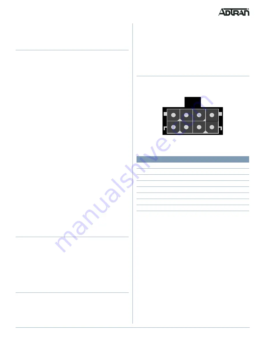
Connect the UPS to the 8-pin MOLEX connector labeled “UPS”
located on the rear of the SFU ONT chassis.
represents
the MOLEX connector.
Figure 2. MOLEX Connector
The UPS Power/Alarm Connections Table, below, provides a pin-
out of the connector.
g
NOTE
If an UPS is being used and the battery is disconnected or
becomes completely discharged, the 424 ONT is not protected
from power outages, and will send a “Battery Missing” alarm to the
OLT.
Pin-Out
Description
Alarm
1
Power Input (+12 VDC)
-
2
UPS Status - On Battery
1
3
UPS Status - Battery Missing
2
4
Signal Return
-
5
Power 12V Return
-
6
UPS Status - Replace Battery
3
7
UPS Status - Low Battery
4
8
No Connection
-
8
7
6
5
4
3
2
1


