2
617101763F1-13A
Installing the Switch
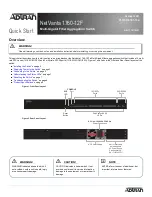
Package Contents
■ NetVanta 1760-12F switch
■ AC power cord
■ DB-9 to RJ-45 cable
■ Micro-USB to USB cable
■ Four adhesive rubber feet
■ Rack Mounting kit (two brackets and eight screws)
■ Quick Start.
Installation Overview
To install the switch, you will need to do the following:
1. Mount the switch
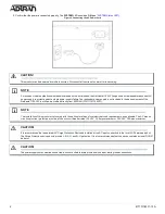
2. Connect AC Power
3. Install SFP+/SFP28 Modules
Installation Steps
To install the NetVanta 1760-12F switch, complete the steps outlined in the following sections.
Mounting the Switch in a 19-inch Rack
To mount the switch into a 19-inch rack, complete the following steps.
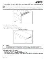
1. Attach the mounting brackets to both sides of the chassis. Insert the provided screws and tighten them with a screwdriver to secure the brackets.
Figure 3. Attaching Brackets to the Switch
2. Position the chassis in the stationary equipment rack. Allow 1-inch of clearance between units.
NOTE
g
Refer to the national, state and local electrical codes for the requirements for power, grounding, wiring, and installation methods.
CAUTION!
f
CAUTION!
f
The NetVanta 1760-12F is intended for indoor use only. Ethernet, PoE cables, and attached equipment are intended for use within the same
building with equipotential bonding, and not intended to be placed in separate buildings or structures. Failure to deploy as described could
result in permanent damage from lightning or other electrical events and voids the warranty.
WARNING!
f
This equipment is not suitable for use in locations where children are likely to be present.

