ADTRAN 17101564F1 Скачать руководство пользователя страница 4

4

617101564F1-13A

3. For the best support of the switch and cables, ensure that the switch is securely attached to wall studs or a firmly attached plywood mounting 

backboard.

Figure 6. Install Screws in the Wall and Hang the Switch on the Screws

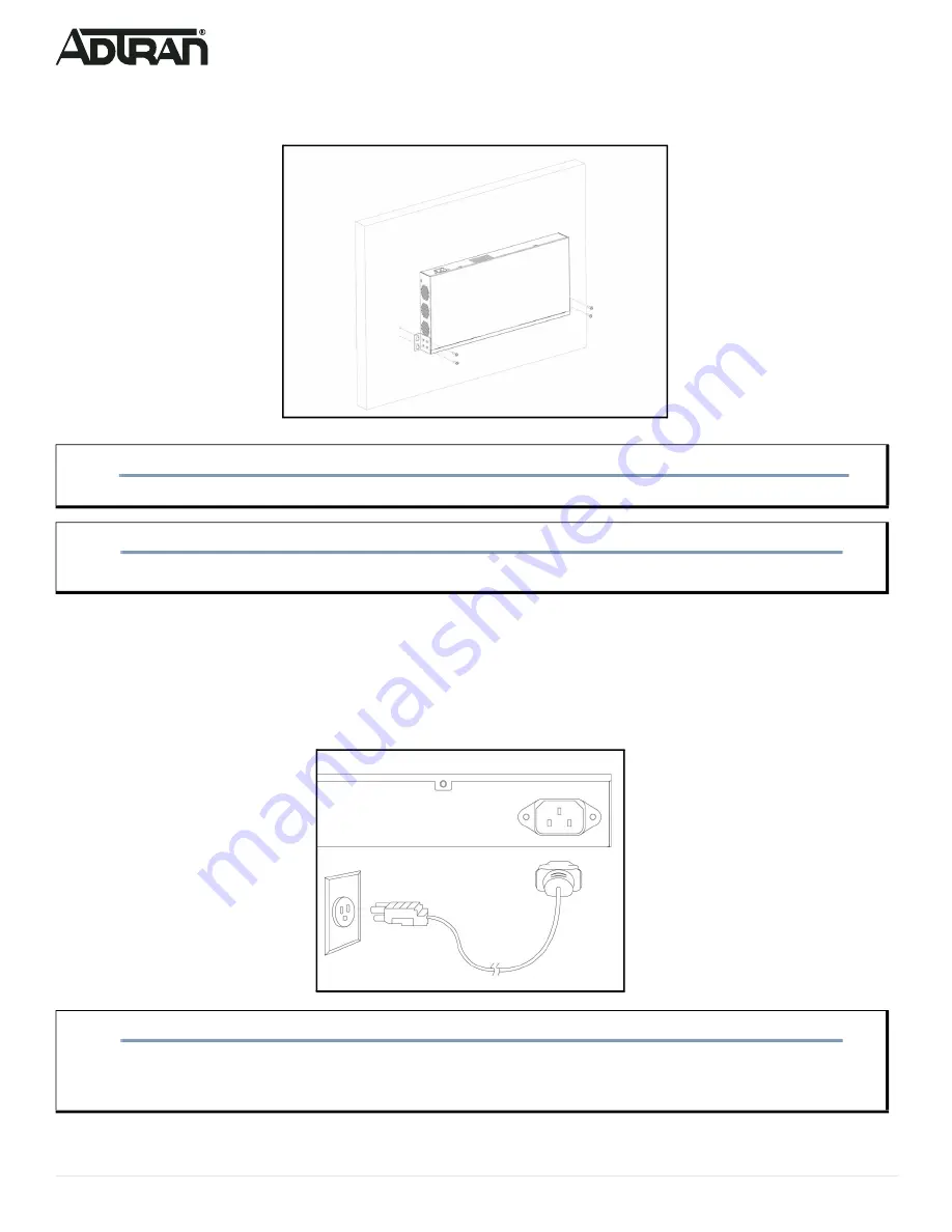
Supplying Power to the Switch

To connect the AC power cord to the switch, complete the following steps.

1. Connect the AC power cord to the AC power receptacle on the rear panel of the switch. 
2. Connect the other end of the AC power cord to a properly grounded AC power outlet. The AC branch circuit socket-outlet must be installed near the 

equipment and must be easily accessible.

3. Confirm that the power is connected properly. The 

SYSTEM

 LED should be ON (see 

“SYSTEM Status LED”

).

Figure 7. Connecting the AC Power Cord

CAUTION!

f

The NetVanta 1560-24 must be mounted in the face-down orientation when wall mounted.

NOTE

g

The wall mount brackets are not supplied with the unit and must be purchased separately from ADTRAN, part number 1700520F1.

NOTE

g

The installation of this product must comply with the national, state and local electrical code requirements, as applicable. The AC branch 

circuit overcurrent protection must be a fuse or circuit breaker rated 125 VAC, 20 Amps maximum or 250 VAC, 16 Amps maximum. A 

readily accessible disconnect device that is suitably approved and rated must be incorporated in the field wiring.

Содержание 17101564F1

Страница 1: ...efore installing or servicing this equipment NetVanta 1560 24 SYSTEM CONSOLE USB RESET 1 2 3 4 5 6 7 8 9 10 11 12 13 14 15 16 17 18 19 20 21 22 23 24 25 26 SYS LED CONSOLE Port 10 100 1000 2500 RJ 45...

Страница 2: ...them with a screwdriver to secure the brackets Figure 3 Attaching Brackets to the Switch 2 Position the chassis in the stationary equipment rack Allow 1 inch of clearance between units NOTE g Refer t...

Страница 3: ...a template install four 8 PAN head screws 0 75 inch using two for each bracket as shown in Figure 6 in the appropriate location on the wall Be aware of the dimensional limitations of the screws 2 Slid...

Страница 4: ...equipment and must be easily accessible 3 Confirm that the power is connected properly The SYSTEM LED should be ON see SYSTEM Status LED Figure 7 Connecting the AC Power Cord CAUTION f The NetVanta 15...

Страница 5: ...AC Surge Protection Device be installed at the AC input connection to the local AC Powered product The Surge Protection device should provide L N L G and N G protection It is also recommended that th...

Страница 6: ...IP address 3 Power up the switch to be initially configured and wait until it has finished its start up processes 4 Connect the PC to any port on the switch using a standard Ethernet cable and check t...

Страница 7: ...atus LEDs The Port Status LEDs indicate the current status of each port NOTE g There are many terminal emulation applications available on the web PuTTY SecureCRT and HyperTerminal are a few examples...

Страница 8: ...tore to Factory Defaults 7 12 seconds Flashing Green All LEDs are ON Symptoms Possible Causes Suggested Solutions System LED is OFF The switch is not receiving power 1 Check if correct power cord is c...

Страница 9: ...g or maintaining always place devices on an approved antistatic mat that is electrically grounded Warranty ADTRAN will replace or repair this product within the warranty period if it does not meet its...

Отзывы: