Call StormTech at
860.529.8188
or
888.892.2694
or visit our website at
www.stormtech.com
for technical and product information.
26
8.0 Outlets for Chambers
Table 9B – Maximum Outlet Flow Rate Capacities from
StormTech Manifolds
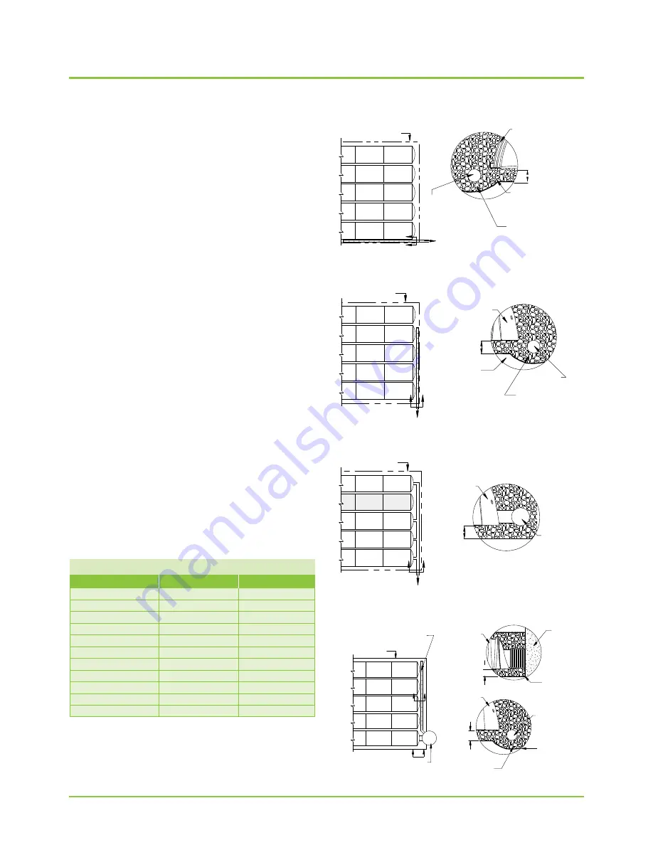
Figure 10 – Underdrain Parallel
Figure 11 – Underdrain Perpendicular
Figure 12 – Outlet Manifold
Figure 13 – Combination Outlet
OUTLET FLOW
PIPE DIA.
FLOW (CFS)
FLOW (L/S)
6” (150 mm)
0.4
11.3
8” (200 mm)
0.7
19.8
10” (250 mm)
1.0
28.3
12” (300 mm)
2.0
56.6
15” (375 mm)
2.7
76.5
18” (450 mm)
4.0
113.3
24” (600 mm)
7.0
198.2
30” (750 mm)
11.0
311.5
36” (900 mm)
16.0
453.1
42” (1050 mm)
22.0
623.0
48” (1200 mm)
28.0
792.9
8.0 OUTLETS FOR STORMTECH CHAMBER SYSTEMS
The majority of StormTech installations are detention
systems and have some type of outlet structure. An outlet
manifold is generally designed to ensure that peak flows
can be conveyed to the outlet structure.
To drain the system completely, an underdrain system is
located at or below the bottom of the foundation stone.
Some beds may be designed with a pitched base to
ensure complete drainage of the system. A grade of ½%
is usually satisfactory.
An outlet pipe may be located at a higher invert within a
bed. This allows a designed volume of water to infiltrate
while excess volumes are outlet as necessary. This is an
excellent method of recharging groundwater, replicating a
site’s pre-construction hydraulics.
Depending on the bed layout and inverts, outlet pipes
should be placed in the embedment stone along the bed’s
perimeter as shown in
Figures 10
and
11
. Solid outlet
pipes should also be used to penetrate the StormTech end
caps at the designed outlet invert as shown in
Figure 12
.
An Isolator Row should not be directly penetrated with an
outlet pipe. For systems requiring higher outlet flow rates,
a combination of connections may be utilized as shown in
Figure 13
.
In detention and retention applications the discharge
of water from the stormwater management system is
determined based on the hydrology of the area and the
hydraulic design of the system. It is the design engineer’s
responsibility to design an outlet system that meets
their hydraulic objectives while following local laws and
regulations.
STORMTECH
CHAMBER
PERFOR ATED
UNDERDRAIN PIPE
ADS 601 NON-WOVEN
GEOTEXTILE (OR EQUAL)
STONE BEDDING
UNDER DRAINAGE
PIPE (PER DESIGN)
STONE BASE
BENEATH
CHAMBER
SECTION A_A
BED PERIMETER
TO OUTLET
CONTROL
STRUCTURE
A
A
BED PERIMETER
TO OUTLET CONTROL
STRUCTURE
B
B
PERFORATED
UNDERDRAIN PIPE
ADS 601
NON-WOVEN
GEOTEXTILE
(OR EQUAL)
STONE BEDDING
UNDER DRAINAGE
PIPE (PER DESIGN)
STONE BASE
BENEATH
CHAMBER
SECTION B_B
STORMTECH
CHAMBER
STORMTECH
CHAMBER
MANIFOLD
OUTLET
PIPING
STONE
BASE
BENEATH
CHAMBER
SECTION C_C
BED PERIMETER
ISOLATOR ROW
TO OUTLET CONTROL
STRUCTURE
C
C
STORMTECH
CHAMBER
STORMTECH
CHAMBER
PERFORATED
UNDERDRAIN PIPE
AASHTO M288
CLASS 2
NON-WOVEN
GEOTEXTILE
STONE BEDDING
UNDER DRAINAGE
PIPE (PER DESIGN)
SECTION B_B
SECTION A_A
FOUNDATION
STONE BENEATH
CHAMBER
FOUNDATION
STONE
BENEATH
CHAMBER
ADS 601
NON-WOVEN
GEOTEXTILE
(OR EQUAL)
OUTLET
CONTROL
STRUCTURE
BED PERIMETER
OUTLET CONTROL STRUCTURE
PER ENIGNEER'S DESIGN
NUMBER AND SIZE OF UNDER-
DRAINS PER ENGINEER DESIGN
B
B
A
A
Содержание StormTech DC-780
Страница 2: ...An company TOOL 2 0 DESIGN ...
Страница 39: ......

