


28
System Layout
Leading
EDGE COMPUTING
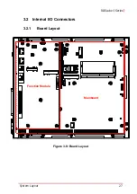
3.2.2
Mainboard Connector Locations
Figure 3-9: Mainboard Connectors
A
Fan connector
J
I
2
C1 connector
B
USB 2.0 dongle
K
Power and Reset header
C
Backplane slot
L
I
2
C0 connector
D
Backplane slot
M
COM port 3 and 4 connectors
E
M.2 connector (for storage)
N
DIO, COM port 5/6, Audio connector
F
DDR4 SO-DIMM slot
O
Speaker connector
G
SIM card socket for Mini PCIe
P
GPS module power header
H
Mini PCIe socket
Q
Battery socket
I
Clear CMOS connector
R
FM board-to-board connector
Table 3-14: Mainboard Connector Legend
A
B
C
D
E
F
G
H
I
J
K
L
M
N
O
P
Q
R
Содержание ROScube-I Series
Страница 8: ...viii List of Tables Leading EDGE COMPUTING This page intentionally left blank ...
Страница 10: ...x List of Figures Leading EDGE COMPUTING This page intentionally left blank ...
Страница 24: ...14 Specifications Leading EDGE COMPUTING This page intentionally left blank ...
Страница 42: ...32 System Layout Leading EDGE COMPUTING This page intentionally left blank ...
Страница 46: ...36 Getting Started Leading EDGE COMPUTING This page intentionally left blank ...
Страница 52: ...42 BIOS Setup Leading EDGE COMPUTING B 2 1 CPU Configuration ...
Страница 94: ...84 Consignes de Sécurité Importante Leading EDGE COMPUTING This page intentionally left blank ...


