Interfaces
25
Q7-BASE
3.9
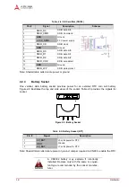
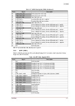
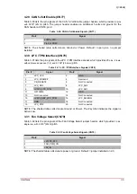
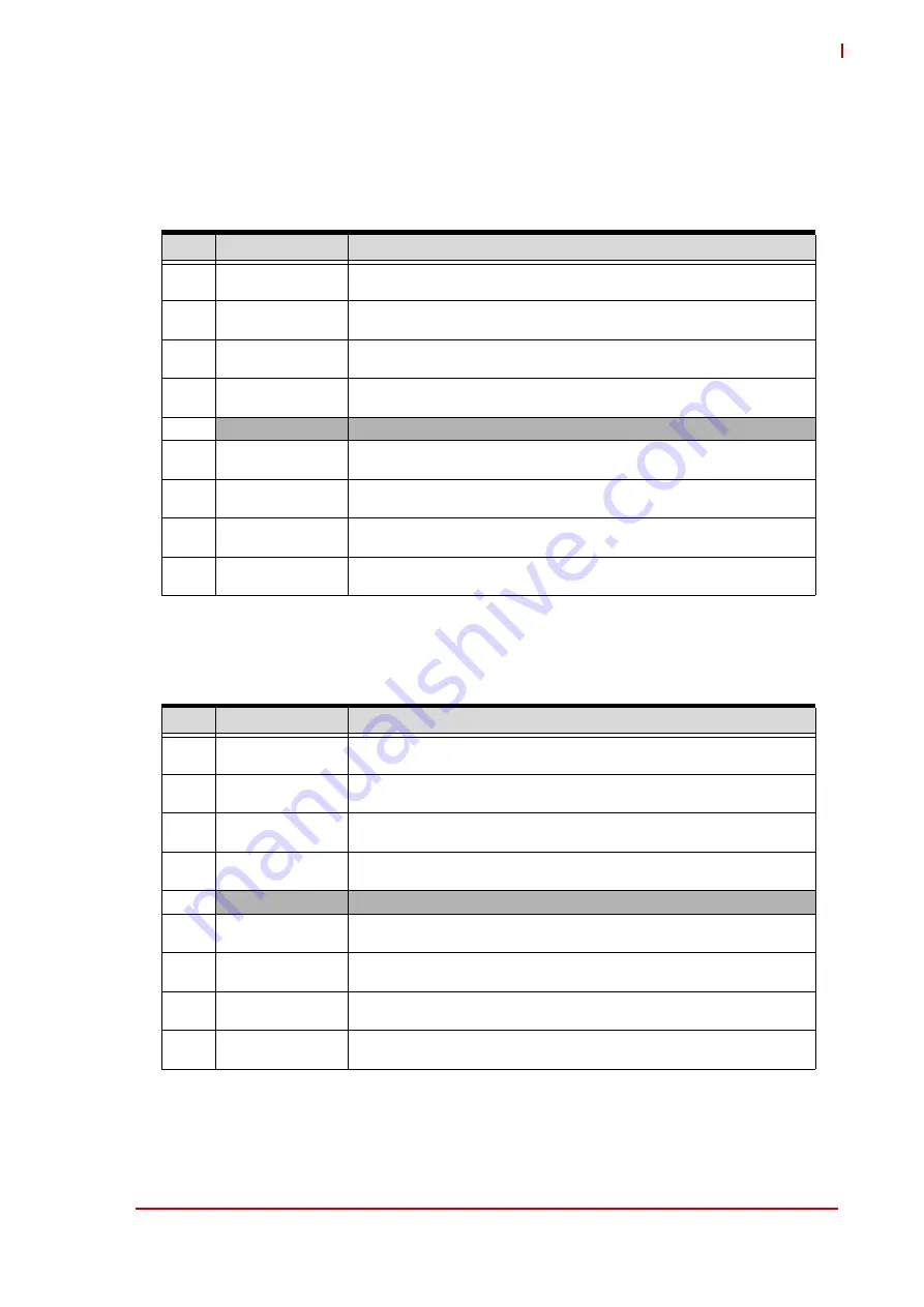
COM1 / COM2 (CN39)
This section describes the signals of the dual, standard DB9 serial port connector for RS232 sig-
nals. Table 3-10 and Table 3-11 list the pin signals of the 4-wire RS232 interface (COM1 and
COM2), which provides a standard dual DB9 connector.
NOTE: Shaded table cell denotes ground. The # symbol indicates the signal is Active Low. This
port supports only RS232.
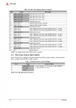
NOTE: Shaded table cell denotes ground. The # symbol indicates the signal is Active Low. This
port supports only RS232.
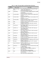
Table 3-10: COM1 Signals (CN39)
Pin #
Signal
Description
1
COM1_DCD#
Data Carrier Detection. An active-low signal indicates the modem or data
set has detected a data carrier.
2
COM1_RXD
Serial Input. This pin is used to transmit serial data out to the
communication link.
3
COM1_TXD
UART A Serial Output. This pin is used to transmit serial data out to the
communication link.
4
COM1_DTR#
UART A Data Terminal Ready. An Active-Low signal informs the modem or
data set that the controller is ready to communicate.
5
COM1_GND
Ground
6
COM1_DSR#
Data Set Ready. An active-low signal indicates the modem or data set is
ready to establish a communication link and transfer data to the UART.
7
COM1_RTS#
UART A Request to Send. An Active-Low signal informs the modem or
data set that the controller is ready to send data.
8
COM1_CTS#
Clear to Send. This is the modem-control input. The function of this pin can
be tested by reading bit 4 of the handshake status register.
9
COM1_RI#
Ring Indicator. An active-low signal indicates that a ring signal is being
received from the modem or the data set.
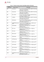
Table 3-11: COM2 Signals (CN39)
Pin #
Signal
Description
1
COM2_DCD#
Data Carrier Detection. An active-low signal indicates the modem or data
set has detected a data carrier.
2
COM2_RXD
Serial Input. This pin is used to transmit serial data out to the
communication link.
3
COM2_TXD
UART B Serial Output. This pin is used to transmit serial data out to the
communication link.
4
COM2_DTR#
UART B Data Terminal Ready. An Active-Low signal informs the modem or
data set that the controller is ready to communicate.
5
COM2_GND
Ground
6
COM2_DSR#
Data Set Ready. An active-low signal indicates the modem or data set is
ready to establish a communication link and transfer data to the UART.
7
COM2_RTS#
UART B Request to Send. An Active-Low signal informs the modem or
data set that the controller is ready to send data.
8
COM2_CTS#
Clear to Send. This is the modem-control input. The function of this pin can
be tested by reading bit 4 of the handshake status register.
9
COM2_RI#
Ring Indicator. An active-low signal indicates that a ring signal is being
received from the modem or the data set.


