background image

86

Important Safety Instructions

X

Never attempt to fix the equipment. Equipment should only 
be serviced by qualified personnel.

A Lithium-type battery may be provided for uninterrupted, backup
or emergency power.

X

Equipment must be serviced by authorized technicians 
when:

Z

The power cord or plug is damaged;

Z

Liquid has penetrated the equipment;

Z

It has been exposed to high humidity/moisture;

Z

It is not functioning or does not function according to the 
user’s manual;

Z

It has been dropped and/or damaged; and/or it has an 
obvious sign of breakage.

WARNING:

Risk of explosion if battery is replaced with one of an incorrect 
type.  Dispose of used batteries appropriately.

Содержание NuPRO-E43

Страница 1: ...Advance Technologies Automate the World Manual Rev 2 00 Revision Date May 13 2016 Part No 50 13075 1000 NuPRO E43 PICMG 1 3 Full Size LGA1151 Intel Core i7 i5 i3 Processor Based SHB...

Страница 2: ...ii Revision History Revision Release Date Description of Change s 2 00 May 13 2016 Initial Release...

Страница 3: ...en if advised of the possibility of such damages Environmental Responsibility ADLINK is committed to fulfill its social responsibility to global environmental preservation through compliance with the...

Страница 4: ...OTE NOTE Additional information aids and tips that help users perform tasks CAUTION Information to prevent minor physical injury component dam age data loss and or program corruption when trying to co...

Страница 5: ...and Dimensions 8 1 7 I O Connectivity 8 1 8 Rear Panel I O Ports 9 1 9 Board Layout 11 1 10 Onboard Connectors 13 1 11 Jumpers Switches 20 2 Getting Started 21 2 1 Package Contents 21 2 2 Installing...

Страница 6: ...ion 58 A 3 12 Intel Bios Guard Technology 59 A 3 13 Network Stack Configuration 60 A 3 14 CSM Configuration 61 A 3 15 System Management 63 A 3 16 Miscellaneous Configuration 68 A 4 Security 69 A 5 Boo...

Страница 7: ...List of Figures vii NuPRO E43 List of Figures Figure 1 1 NuPRO E43 Block Diagram 5 Figure 1 2 Board Dimensions 8 Figure 1 3 Rear Panel I O Ports 9 Figure 1 4 Board Layout 11...

Страница 8: ...viii List of Figures This page intentionally left blank...

Страница 9: ...List of Tables ix NuPRO E43 List of Tables Table 1 1 NuPRO E43 I O Connectivity 9 Table 1 2 Rear Panel I O Legend 10 Table 1 3 Board Layout Legend 12...

Страница 10: ...x List of Tables This page intentionally left blank...

Страница 11: ...ed up to a maximum of 32GB on two DIMM slots These advanced features coupled with PCI Express x16 expan sion capability dual PCI Express based Gigabit Ethernet SATA 6 Gb s and USB 3 0 support make the...

Страница 12: ...LGA1151 2C 4T Intel Core i3 6100TE 2 7GHz 4M cache 14nm 35W TDP LGA1151 2C 4T Intel Pentium G4400 3 3GHz 3M cache 14nm 65W TDP LGA1151 2C 2T Intel Pentium G4400TE 2 9GHz 3M cache 14nm 35W TDP LGA1151...

Страница 13: ...2x PCIe x8 or 1x PCIe x8 2x PCIe x4 to backplane based on backplane 1x PCIe x4 to backplane and 4x PCI to backplane USB 8x USB 3 0 2 on rear I O 6 onboard box header 4x USB 2 0 to backplane LPT Port...

Страница 14: ...RJ45 Interface PCIe x1 bus iAMT Support iAMT 11 Wake On LAN Support on LAN1 SEMA SEMA support with BMC SEMA Cloud Form Factor Full sized PICMG 1 3 system host board Dimensions 338 mm x 126 mm L x W O...

Страница 15: ...ntroller sup ports dual channel DDR4 and Intel HD Graphics is integrated onboard the CPU The CPU provides a PCI Express x16 for exter nal graphics or expansion Direct Media Interface DMI and Flexi ble...

Страница 16: ...ed to the PCI E bus of the Q170 PCH with Intel AMT 11 I219LM on LAN1 Wake on LAN and PXE supported Serial ATA The NuPRO E43 provides four Serial ATA ports with data transfer rates of up to 6 0 GB s In...

Страница 17: ...ates a reboot Trusted Platform Module The NuPRO E43 optionally supports TPM ver 1 2 Trusted Plat form Module for secure storage of keys passwords and digital certificates Systems supporting TPM offer...

Страница 18: ...millimeters I O Bracket Onboard Edge Connector Remarks VGA Y DB 15 DVI D Y Cable w bracket optional LAN1 2 RJ 45 Y Act Link Speed LEDs PS 2 KB MS Y Cable w bracket optional USB rear panel 2 USB 3 0 US...

Страница 19: ...Rear Panel I O Ports Figure 1 3 Rear Panel I O Ports SATA 4 PCIe x4 Y PCIe x16 Y PCI 32bit 33MHz Y via ITE IT8892 Connector Description A LAN1 RJ 45 Gigabit Ethernet supports Intel AMT B LAN2 RJ 45 Gi...

Страница 20: ...0 ports Pin Signal Name 1 USB3 0_P5VA 2 USB2_CMAN 3 USB2_CMAP 4 GND 5 USB3A_CMRXN 6 USB3A_CMRXP 7 GND 8 USB3A_CMTXN 9 USB3A_CMTXP Pin 10BASE T 100BASE TX 1000BASE T 1 TX BI_DA 2 TX BI_DA 3 RX BI_DB 4...

Страница 21: ...Linked Green 100 Mb connection Blinking Data Activity Amber 1 Gb connection Pin Signal Pin Signal 1 Red 9 5 V 2 Green 10 Ground 3 Blue 11 NC 4 NC 12 DDC DAT 5 Ground 13 HSYNC 6 Ground 14 VSYNC 7 Grou...

Страница 22: ...35 USER system panel pin header F CN34 DVI DVI D G Top down CN30 CN31 CN32 CN33 SATA 0 SATA 1 SATA 2 SATA 3 H CN26 USB3 0 3 4 I CN27 USB3 0 5 6 J CN28 USB3 0 7 8 K CN22 LPT L CN9 COM C M CN10 COM D N...

Страница 23: ...5 CN7 8 Pin RS 232 Signal 1 DCD 2 DSR 3 RXD 4 RTS 5 TXD 6 CTS 7 DTR 8 RI 9 GND 10 NC COMA COM1 COMB COM2 COMC COM3 COMD COM4 Connector CN7 CN8 CN9 CN10 Pitch 2 00 mm 2 00 mm 2 00 mm 2 00 mm Pin RS 422...

Страница 24: ...ignal 1 P5V_USB3B 20 NC 2 S_USB3_RN3_R 19 P5V_USB3B 3 S_USB3_RP3_R 18 S_USB3_RN4_R 4 GND 17 S_USB3_RP4_R 5 S_USB3_TN3_R 16 GND 6 S_USB3_TP3_R 15 S_USB3_TN4_R 7 GND 14 S_USB3_TP4_R 8 S_USB2_N2_R 13 GND...

Страница 25: ...DVI D Onboard Connector CN34 Pin Signal 1 GND 2 GND 3 TMD_CKP 4 TMD_N2 5 TMD_CKN 6 TMD_P2 7 GND 8 GND 9 TMD_SCL 10 TMD_N1 11 TMD_SDA 12 TMD_P1 13 GND 14 GND 15 TMD_HPD 16 TMD_N0 17 5V_PSU_DVI 18 TMD_P...

Страница 26: ...5 V Power 3 TMDS Data2 4 Shield 15 GND 4 TMDS Data4 16 Hot Plug Detect 5 TMDS Data4 17 TMDS Data0 6 DDC Clock SCL 18 TMDSData0 7 DDC Data SDA 19 TMDS Data0 5 Shield 8 Analog vertical sync 20 TMDS Data...

Страница 27: ...daughter board Pin Signal 1 KBCLK_R 2 KBDATA_R 3 MSCLK_R 4 MSDATA_R 5 GND 6 KM_VCC Pin Signal 1 GND 2 TXP 3 TXN 4 GND 5 RXN 6 RXP 7 GND Pin Signal Function 1 GND Ground 2 AUD_BCLK Audio Clock 3 GND G...

Страница 28: ...speakers and LEDs Fan Connector FAN1 Pin Signal 1 GND 2 SPKR 3 RSTBTN 4 NC 5 NC 6 NC 7 GND 8 5V_PSU 9 PWRBTN 10 NC 11 NC 12 GND 13 NC 14 KEYLOCK 15 HLED 16 PLED 17 HLED_POWER 18 NC 19 NC 20 5V_PSU Pin...

Страница 29: ...system 6 Re short pins 1 2 and power up the system Clear RTC Jumper CN42 To clear the BIOS settings and data time SRTCRST 1 Power down and disconnect power from the system 2 Short pins 2 3 on CN42 3...

Страница 30: ...20 Introduction This page intentionally left blank...

Страница 31: ...cable with bracket 2 0 mm pitch 2 2 Installing the CPU The NuPRO E43 supports an Intel Core i7 i5 i3 or Pentium processor in an LGA1151 socket WARNING The NuPRO E43 must be protected from static disch...

Страница 32: ...install the CPU 1 Press down on the locking arm A then push it away from the socket to disengage it from the retention tab B 2 Raise the locking arm to unlock the load plate 3 Lift the load plate to u...

Страница 33: ...n Position the CPU over the socket matching the notches on the sides of the CPU with the alignment keys on the socket A The golden triangle on the CPU must be positioned at the corner of the socket wi...

Страница 34: ...t has cutouts for your fingers to fit into 6 Gently lower the load plate Make sure the front edge of the plate is under the screw as indicated 7 Lower the locking arm and fasten it to the retention ta...

Страница 35: ...e to the CPU fan connector on the SHB labeled FAN1 2 4 Installing Memory Modules The NuPRO E43 supports up to 32 GB of DDR4 2133 MHz memory on two DIMM sockets DDR4 modules have a 288 pin footprint co...

Страница 36: ...le installed per channel must be the same DIMMA0 DIMMB0 X It is recommended that you install DIMMs with the same CAS latency For maximum compatibility install memory modules with the same brand model...

Страница 37: ...Getting Started 27 NuPRO E43 4 Insert the module firmly into the slot until the retaining clips snap back inwards and the module is securely seated Break Notch...

Страница 38: ...com and install X Chipset X Display X Ethernet X Rapid Storage X USB 3 0 X Management Engine WARNING In order to enable RAID or AHCI mode you must pre install the Intel Rapid Storage Technology drive...

Страница 39: ...sic navigation for the AMIBIOS EFI BIOS setup utility A 1 Entering the BIOS To enter the setup screen follow these steps 1 Power on the motherboard 2 Press Delete when the prompt appears A 2 Main Menu...

Страница 40: ...e time Use Tab to switch between time elements A 3 Advanced Menu Accesses CPU Configuration Memory Configuration System Agent SA Configuration Graphics Configuration PCI Express Configuration USB Conf...

Страница 41: ...BIOS Setup 31 NuPRO E43 Network Stack Configuration CSM Configuration System Man agement Miscellaneous Configuration A 3 1 CPU Configuration...

Страница 42: ...timized for Hyper Threading Technology When Disabled only one thread per enabled core is enabled Active Processor Cores Number of cores to be enabled in each processor package Intel Virtualization Tec...

Страница 43: ...urbo Mode CPU C states Enables disables CPU C states CState Pre Wake Disable sets bit 30 of POWER_CTL MSR 0x1FC to 1 to disable the Cstate Pre Wake Package C State limit Package C State limit CPU DTS...

Страница 44: ...t from the factory TCC activation temperature ACPI 3 0 T States Enables disables ACPI 3 0 T States Intel TXT LT Support Enables or Disables Intel TXT LT support A 3 2 Memory Configuration Memory Remap...

Страница 45: ...O E43 A 3 3 System Agent SA Configuration VT d Enables VT d capability Above 4GB MMIO BIOS assignment Enables disables Memory MappedIO BIOS assignment over 4GB disabled automatically when Aperture Siz...

Страница 46: ...A 3 4 Graphics Configuration Primary Display Sets the Primary Display from among IGFX PEG PCIE Internal Graphics Keeps IGFX enabled based on the setup options GTT Size Sets GTT size Aperture Size Sets...

Страница 47: ...DVMT Total Gfx Mem Sets DVMT5 0 total graphic memory size used by the internal graphics device A 3 5 PCI Express Configuration PCI Express port allocation B0 to B3 depends on backplane design whether...

Страница 48: ...aximum speed from among Auto Gen1 Gen2 and Gen3 Max Payload size Appears if a PEG 1 device is present Sets PEG 1 maximum payload size from Auto Default Device Capability or forced to 128 256 bytes Peg...

Страница 49: ...Default Device Capability or forced to 128 256 bytes Peg 3 Max Link Speed Sets PEG 3 maximum speed from among Auto Gen1 Gen2 and Gen3 Max Payload size Appears if a PEG 3 device is present Sets PEG 3...

Страница 50: ...Setup PCIe Speed Sets PCI Express port speed from among Auto Gen1 Gen2 and Gen3 Detect Non Compliance Device Detects non compliant PCI Express device If enabled increases POST duration A 3 6 USB Confi...

Страница 51: ...s for faster enumeration USB Port Disable Override Selectively enables disables the corresponding USB port from reporting a device connection to the controller USB3 Rear Port 1 to USB3 Rear Port 2 Ena...

Страница 52: ...A1 to USB2 BOX Header A2 Enables disables port USB2 BOX Header B1 to USB2 BOX Header B2 Enables disables port USB2 BOX Header C1 to USB2 BOX Header C2 Enables disables port SHB Connector C USB0 to SHB...

Страница 53: ...ontrol Bulk and Interrupt transfers from among 1 5 10 and 20 sec Device reset timeout Sets USB mass storage device Start Unit command timeout from among 10 20 30 and 40 sec Device power up delay Sets...

Страница 54: ...roller s Enables disables SATA Device SATA Mode Selection Determines how SATA controller s operate Alternate ID Appears if SATA is in RAID mode Reports alternate device ID Aggressive LPM Support Enabl...

Страница 55: ...the maximum speed the SATA controller can support from among Default Gen1 Gen2 and Gen3 Port 0 to Port 3 Enables disables SATA port A 3 7 1 Software Feature Mask Configuration RAID0 Enables disables...

Страница 56: ...10 Enables disables RAID10 feature RAID5 Enables disables RAID5 feature A 3 8 Onboard Device Configuration COM1 to COM4 Enables disables individual COM ports COM1 Control Sets COM1 mode from among RS2...

Страница 57: ...ort mode from among STD Printer Mode SPP Mode EPP 1 9 and SPP Mode EPP 1 7 and SPP Mode LAN 1 Intel I219 Enables disables LAN 1 LAN 1 I219 Launch PXE OpROM Enables disables Boot Option for Legacy Netw...

Страница 58: ...48 BIOS Setup A 3 8 1 Serial Port Console Redirection...

Страница 59: ...onsole redirection Console Redirection Settings Depends on Console Redirection setting Specify how the host computer and the remote console computer in use exchange data Both computers should have the...

Страница 60: ...50 BIOS Setup COM2 Console Redirection Settings COM3 Console Redirection Settings...

Страница 61: ...BIOS Setup 51 NuPRO E43 COM4 Console Redirection Settings COM PCI Console Redirection Settings...

Страница 62: ...t with the data bits to detect transmission errors Mark and Space Parity do not allow error detection and can be used as an additional data bit ANSI Extended ASCII character set VT100 ASCII character...

Страница 63: ...g buffers are full a Stop signal stops the ANSI Extended ASCII character set VT100 ASCII character set Enables VT UTF8 combination key support for ANSI VT100 termi nals Recorder Mode When enabled only...

Страница 64: ...t Port Microsoft Windows Emergency Management Services EMS allows remote management of Windows Server OS through a serial port from among COM1 COM2 COM3 COM4 and COM PCI Bus0 Dev22 Func3 Terminal Type...

Страница 65: ...9200 57600 and 115200 Flow Control Can prevent data loss from buffer overflow When sending data if the receiving buffers are full a Stop signal stops the data flow Once the buffers are empty a Start s...

Страница 66: ...amicTime waking the system at the current time one minute PCIe Slot Wake Enables disables PCI Express Slot wake function Onboard LAN Wake Enables disables onboard LAN wake function PCI SIO Wake Enable...

Страница 67: ...ice Support Enables disables BIOS support for security device When dis abled OS will not show the Security Device and TCG EFI protocol and INT1A interface will not be available TPM State Enables disab...

Страница 68: ...Intel AMT Enables disables Intel Active Management Technology BIOS Extension While iAMT H W is always enabled this option controls the BIOS extension execution If enabled additional firmware is requi...

Страница 69: ...BIOS Setup 59 NuPRO E43 BIOS Hotkey Pressed OEMFLag Bit 1 Enables disables BIOS hotkey A 3 12 Intel Bios Guard Technology Intel Bios Guard Support Enables disables Intel BIOS Guard support...

Страница 70: ...UEFI Network Stack Ipv4 PXE Support Appears if Network Stack is enabled Enables Ipv4 PXE boot support if disabled no IPV4 PXE boot option is created Ipv6 PXE Support Appears if Network Stack is enabl...

Страница 71: ...ed Sets wait duration to press ESC key to abort PXE boot A 3 14 CSM Configuration CSM Support Enables disables CSM Support GateA20 Active UPON REQUEST to GA20 can be disabled using BIOS services ALWAY...

Страница 72: ...or Keep Cur rent Network Controls execution of UEFI and legacy PXE OpROM Storage Controls execution of UEFI and legacy storage OpROM Video Controls execution of UEFI and legacy video OpROM Other PCI d...

Страница 73: ...BIOS Setup 63 NuPRO E43 A 3 15 System Management A 3 15 1 Board Information...

Страница 74: ...64 BIOS Setup A 3 15 2 Temperatures and Fan Speed...

Страница 75: ...BIOS Setup 65 NuPRO E43 A 3 15 3 Hardware Monitor A 3 15 4 Runtime Statistics...

Страница 76: ...66 BIOS Setup A 3 15 5 Flags A 3 15 6 Power Up...

Страница 77: ...ich resets the sys tem a set time after power up Timeout Appears if Power Up Watchdog is enabled Sets the time before the Power Up Watchdog resets the system from between 24 and 65535 A 3 15 7 Smart F...

Страница 78: ...ure From 0 to 100 C PWM Level From 0 to 100kHz A 3 16 Miscellaneous Configuration High Precision Timer Enables disables High Precision Event timer Port 80h Redirection Sets destination for Port 80h cy...

Страница 79: ...UTO retaining hw default with no BIOS override from 0 0 to 2 0 A 4 Security In addition to allowing supervisor user passwords to be set changed or cleared the following settings are available Administ...

Страница 80: ...byte bank of RTC RAM are locked BIOS Lock Enables disables PCH BIOS Lock Enable BLE bit A 5 Boot Setup Prompt Timeout Sets number of seconds to wait for setup activation key with 65535 0xFFFF indicat...

Страница 81: ...Y or UEFI Boot Options 1 to 8 Sets the system boot order UEFI XXXXXXXX Drive BBS Priorities Specifies the Boot Device Priority sequence from available UEFI XXXXXXXX drives appearing when boot mode is...

Страница 82: ...Exit Exits system setup without saving any changes Save Changes and Reset Resets the system after saving changes Discard Changes Discards all changes made to any setup options Restore Defaults Reverts...

Страница 83: ...ults Saves all changes as User Defaults Restore User Defaults Reverts to user defaults for all setup options Launch EFI Shell from filesystem device Initiates launch of the EFI Shell application Shell...

Страница 84: ...74 BIOS Setup This page intentionally left blank...

Страница 85: ...r and application have been installed and that during installation the Install EAPI option was enabled 1 Include the relevant header files ifndef _WIN32 include linux EApiOs h else _WIN32 include winn...

Страница 86: ...76 Watchdog Timer This page intentionally left blank...

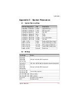
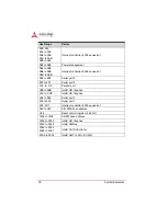
Страница 87: ...BIOS Area Upper E8000 EFFFF 32 kB System BIOS Area Lower C0000 E7FFF 160 kB PCI expansion ROM area A0000 BFFFF 128 kB Video Buffer SMM space 00000 9FFFF 640 kB DOS Area Hex Range Device 020 to 021 024...

Страница 88: ...ial port 2 378 to 37F Parallel port 3B0 to 3BB Intel HD Graphics 3C0 to 3DF Intel HD Graphics 3E8 to 3EF Serial port 3 3F8 to 3FF Serial port 1 4D0 4D1 Interrupt controller 8259 equivalent A00 to A3F...

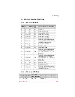
Страница 89: ...nd internal PCI ACPI devices 7 PIRQA Yes No Serial Port 4 COM4 8 No No No Real time clock 9 PIRQA Yes No Cascade to IRQ2 10 PIRQA Yes Yes Option for configurable sources including PIRQx GPIO eSPI inte...

Страница 90: ...for configurable sources including GPIO eSPI internal ACPI PCI devices SCI TCO HPET 2 12 No Yes No No PS 2 Mouse 13 No No No No Math Processor 14 No Yes No No Parallel Port LPT 15 No Yes No Yes Optio...

Страница 91: ...evices and HPET 21 No No No Yes Option for configurable sources including internal PIRQ E H GPIO eSPI SCI TCO internal ACPI PCI devices and HPET 22 No No No Yes Option for configurable sources includi...

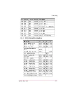
Страница 92: ...17h 00h Internal Intel SATA controller 00h 1Ch 00h Internal PCI Express Root port 1 00h 1Ch 04h Internal PCI Express Root port 5 00h 1Ch 05h Internal PCI Express Root port 6 00h 1Ch 06h Internal PCI...

Страница 93: ...Port INTC INTD INTA INTB Intel Integrated Graphics Device INTA Intel USB XHCI Controller INTA INTD Intel Thermal Controller INTC Intel I2C Controller 0 INTA INTB INTC INTD Intel MEI INTA INTB INTC IN...

Страница 94: ...CIE X4 X1 SLOT 1 INTA INTB INTC INTD PCIE X1 SLOT 2 INTB INTC INTD INTA PCIE X1 SLOT 3 INTC INTD INTA INTB PCIE X1 SLOT 4 INTD INTA INTB INTC PCIE To PCI Bridge IT8892E INTA INTB INTC INTD PCI SLOT 1...

Страница 95: ...urn off power and unplug any power cords cables X To avoid electrical shock and or damage to equipment Z Keep equipment away from water or liquid sources Z Keep equipment away from high heat or high h...

Страница 96: ...viced by authorized technicians when Z The power cord or plug is damaged Z Liquid has penetrated the equipment Z It has been exposed to high humidity moisture Z It is not functioning or does not funct...

Страница 97: ...el 86 21 5132 8988 Fax 86 21 5132 3588 Email market adlinktech com ADLINK Technology Beijing Address 1 E 801 100085 Rm 801 Power Creative E No 1 Shang Di East Rd Beijing 100085 China Tel 86 10 5885 86...

Страница 98: ...800 0585 Tel 82 31 786 0585 Fax 82 31 786 0583 Email korea adlinktech com ADLINK Technology Singapore Pte Ltd Address 84 Genting Lane 07 02A Cityneon Design Centre Singapore 349584 Tel 65 6844 2261 F...

Отзывы: