background image

Table of Contents

 v

GIE64+

Table of Contents

Revision History......................................................................  ii

Preface ....................................................................................  iii

List of Figures .......................................................................  vii

List of Tables..........................................................................  ix

1 Introduction ........................................................................  1

1.1

Overview..............................................................................  1

1.2

Features...............................................................................  1

1.3

Applications .........................................................................  2

1.4

Specifications.......................................................................  2

1.4.1

Power over Ethernet Port ........................................... 2

1.4.2

General Specifications................................................ 3

1.5

I/O and Indicators ................................................................  4

1.5.1

RJ-45 Ethernet Port.................................................... 5

1.5.2

Status LEDs................................................................ 6

1.5.3

Power Connector........................................................ 7

1.5.4

Card ID Switch (S1).................................................... 8

1.5.5

Onboard LED Status Indicators................................ 10

2 Getting Started .................................................................  13

2.1

Unpacking Checklist ..........................................................  13

2.2

Installation..........................................................................  13

Important Safety Instructions ..............................................  15

Getting Service......................................................................  17

Содержание GIE64+

Страница 1: ...Advance Technologies Automate the World Manual Rev 4 00 Revision Date July 17 2013 Part No 50 11245 1030 GIE64 4 CH PoE GigE Vision Interface Card User s Manual ...

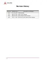
Страница 2: ...y Revision Release Date Description of Change s 2 00 Feb 24 2012 Initial release 2 10 Mar 23 2012 Minor spec changes 3 00 May 30 2013 New product version release 4 00 July 17 2013 Revision to new product version release ...

Страница 3: ...n if advised of the possibility of such damages Environmental Responsibility ADLINK is committed to fulfill its social responsibility to global environmental preservation through compliance with the Euro pean Union s Restriction of Hazardous Substances RoHS direc tive and Waste Electrical and Electronic Equipment WEEE directive Environmental protection is a top priority for ADLINK We have enforced...

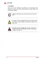
Страница 4: ...NOTE NOTE Additional information aids and tips that help users perform tasks CAUTION Information to prevent minor physical injury component dam age data loss and or program corruption when trying to com plete a task WARNING Information to prevent serious physical injury component damage data loss and or program corruption when trying to complete a specific task ...

Страница 5: ...tions 2 1 4 Specifications 2 1 4 1 Power over Ethernet Port 2 1 4 2 General Specifications 3 1 5 I O and Indicators 4 1 5 1 RJ 45 Ethernet Port 5 1 5 2 Status LEDs 6 1 5 3 Power Connector 7 1 5 4 Card ID Switch S1 8 1 5 5 Onboard LED Status Indicators 10 2 Getting Started 13 2 1 Unpacking Checklist 13 2 2 Installation 13 Important Safety Instructions 15 Getting Service 17 ...

Страница 6: ...vi Table of Contents This page intentionally left blank ...

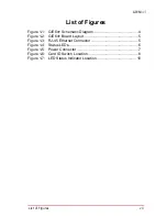
Страница 7: ... Figure 1 1 GIE64 Schematic Diagram 4 Figure 1 2 GIE64 Board Layout 5 Figure 1 3 RJ 45 Ethernet Connector 5 Figure 1 4 Status LEDs 6 Figure 1 5 Power Connector 7 Figure 1 6 Card ID Switch Location 8 Figure 1 7 LED Status Indicator Location 10 ...

Страница 8: ...viii List of Figures This page intentionally left blank ...

Страница 9: ...le 1 1 Board Layout Legend 5 Table 1 2 RJ 45 Ethernet Port Connector Signals 6 Table 1 3 Status LED Legend 7 Table 1 4 Power Connector Pin Assignments 7 Table 1 5 ID Switch Position Legend 9 Table 1 6 LED Status Indicator Display Definitions 11 ...

Страница 10: ...x List of Tables This page intentionally left blank ...

Страница 11: ...speed backbone network for data transfers significantly exceeding those of a single Gigabit Ethernet port or device Finally the GIE64 provides a SmartPoe API allowing remote on off switching of PoE status via programming with no require ment for cable plug connection disconnection 1 2 Features X IEEE802 3af 48 V 15 4 W per channel compliant support ing classes 0 1 2 3 4 X Powered Device PD auto de...

Страница 12: ...ol MAC and physical layer PHY ports X Full controller compliance with IEEE 802 3 af standard for maximum 15 4 watts with power up to 48 V over existing CAT 5 Ethernet infrastructure with no modifications required X Standard IEEE 802 3 Ethernet interface provided for 1000BASE T 100BASE TX and 10BASE T applications 802 3 802 3u and 802 3ab NOTE NOTE The GIE64 Function Library Reference can be downlo...

Страница 13: ...ports 1 port PCIe X4 for GigE Vision Differential Output Peak to Peak Voltage 0 8 V to 1 2 V Differential Input Peak to Peak Voltage 0 175 V to 1 2 V Input voltage for PERST WAKE and SMBus 0 75 V to 4 05 V Gigabit Ethernet LAN chip Intel 82574L PCIe v1 1 2 5GT s Gigabit Ethernet Ports 4 PoE Signal Max Output Power 15 4 W per channel IEEE 802 3af compliant PoE Output Voltage 44 to 48 V PoE port pos...

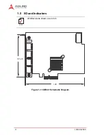
Страница 14: ...4 Introduction 1 5 I O and Indicators Figure 1 1 GIE64 Schematic Diagram NOTE NOTE All dimensions shown are in mm 101 26 145 ...

Страница 15: ... 5 GIE64 Figure 1 2 GIE64 Board Layout Table 1 1 Board Layout Legend 1 5 1 RJ 45 Ethernet Port Figure 1 3 RJ 45 Ethernet Connector A PCIe lane B RJ 45 Ethernet Ports C PoE Status LED D Power Connector A A B C D 1 8 ...

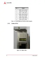
Страница 16: ... 2 RJ 45 Ethernet Port Connector Signals 1 5 2 Status LEDs Figure 1 4 Status LEDs Pin Signal 1 MDI0 PoE_DC48V 2 MDI0 PoE_DC48V 3 MDI1 PoE_DC0V 4 MDI2 PoE_DC48V 5 MDI2 PoE_DC48V 6 MDI1 PoE_DC0V 7 MDI3 PoE_DC0V 8 MDI3 PoE_DC0V ...

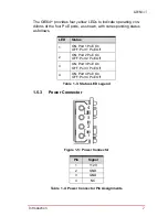
Страница 17: ... status as follows Table 1 3 Status LED Legend 1 5 3 Power Connector Figure 1 5 Power Connector Table 1 4 Power Connector Pin Assignments LED Status 1 ON Port 1 PoE On OFF Port 1 PoE Off 2 ON Port 2 PoE On OFF Port 2 PoE Off 3 ON Port 3 PoE On OFF Port 3 PoE Off 4 ON Port 4 PoE On OFF Port 4 PoE Off Pin Signal 1 12V 2 GND 3 GND 4 NC 4 3 2 1 ...

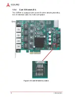
Страница 18: ...8 Introduction 1 5 4 Card ID Switch S1 The GIE64 is equipped with a card ID switch allowing identifica tion of individual cards in a multi card system Figure 1 6 Card ID Switch Location ...

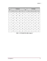
Страница 19: ...der 4 3 2 1 4 3 2 1 0 off off off off 8 on off off off 1 off off off on 9 on off off on 2 off off on off 10 on off on off 3 off off on on 11 on off on on 4 off on off off 12 on on off off 5 off on off on 13 on on off on 6 off on on off 14 on on on off 7 off on on on 15 on on on on ...

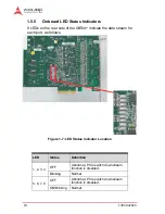
Страница 20: ... GIE64 indicate the data stream for each port as follows Figure 1 7 LED Status Indicator Location LED Status Definition 1 2 3 4 OFF Abnormal PCIe switch downstream function is disabled Blinking Normal 5 6 7 8 OFF Abnormal PCIe switch downstream function is disabled ON Blinking Normal ...

Страница 21: ...ON Abnormal PCIe switch has unexpected error CAUTION Default status of LEDs 1 4 is blinking for LEDs 5 8 lit or blink ing and LED 9 OFF If the GIE64 is malfunctioning and abnormal LED behavior board damage may haver occurred Please contact your distributor or agent LED Status Definition ...

Страница 22: ...12 Introduction This page intentionally left blank ...

Страница 23: ...PCI express bus 1 Remove the computer cover according to the computer manual 2 Remove the slot cover if any 3 Carefully position the GIE64 in the selected PCI express slot If installing in a tower computer align the board with the board slots 4 Press the board firmly but carefully into the connector 5 Anchor the board with the screw 6 Plug the cable into the PoE power connector 7 Connect the devic...

Страница 24: ...14 Getting Started 8 Power up the computer NOTE NOTE The GIE64 can be installed in a PCI Express x4 x8 or x16 slot Please download the Intel 82574L driver from downloadcenter intel com ...

Страница 25: ...rn off power and unplug any power cords cables X To avoid electrical shock and or damage to equipment Z Keep equipment away from water or liquid sources Z Keep equipment away from high heat or high humidity Z Keep equipment properly ventilated do not block or cover ventilation openings Z Make sure to use recommended voltage and power source settings Z Always install and operate equipment near an e...

Страница 26: ...viced by authorized technicians when Z The power cord or plug is damaged Z Liquid has penetrated the equipment Z It has been exposed to high humidity moisture Z It is not functioning or does not function according to the user s manual Z It has been dropped and or damaged and or Z It shows obvious signs of breakage WARNING Risk of explosion if battery is replaced with one of an incorrect type Dispo...

Страница 27: ...ng Chun Rd Zhangjiang Hi Tech Park Pudong New Area Shanghai 201203 China Tel 86 21 5132 8988 Fax 86 21 5132 3588 Email market adlinktech com ADLINK Technology Beijing Address ҀᏖ ऎϞഄϰ䏃 1 োⲜ ࡼ ॺ E ᑻ 801 ᅸ 100085 Rm 801 Power Creative E No 1 Shang Di East Rd Beijing 100085 China Tel 86 10 5885 8666 Fax 86 10 5885 8626 Email market adlinktech com ADLINK Technology Shenzhen Address ഇᏖफቅऎ ᡔುफऎ催ᮄफϗ䘧 ᄫᡔᴃು...

Страница 28: ...r B D 1675 12 Seocho Dong Seocho Gu Seoul 137 070 Korea Tel 82 2 2057 0565 Fax 82 2 2057 0563 Email korea adlinktech com ADLINK Technology Singapore Pte Ltd Address 84 Genting Lane 07 02A Cityneon Design Centre Singapore 349584 Tel 65 6844 2261 Fax 65 6844 2263 Email singapore adlinktech com ADLINK Technology Singapore Pte Ltd Indian Liaison Office Address 1st Floor 50 56 Between 16th 17th Cross M...

Отзывы: