8
Connectors
Note:
For pins 11, 14 and 16 of Jn2, BUSMODE is set to
capable of performing PCI protocol
:
39
GND
LOCK#
40
39
PERR#
GND
40
41
NC
NC
42
41
+3.3V
SERR#
42
43
PAR
GND
44
43
C/BE[1]#
GND
44
45
V(I/O)
AD[15]
46
45
AD[14]
AD[13]
46
47
AD[12]
AD[11]
48
47
M66EN
AD[10]
48
49
AD[09]
+5V
50
49
AD[08]
+3.3V
50
51
GND
C/BE[0]#
52
51
AD[07]
NC
52
53
AD[06]
AD[05]
54
53
+3.3V
NC
54
55
AD[04]
GND
56
55
PMC-RSVD1
GND
56
57
V(I/O)
AD[03]
58
57
PMC-RSVD2
PMC-RSVD3
58
59
AD[02]
AD[01]
60
59
GND
PMC-RSVD4
60
61
AD[00]
+5V
62
61
ACK64#
+3.3V
62
63
GND
REQ64#
64
63
GND
NC
64
BUSMODE[4:2]#
L L H
Jn3 (64 Bit)
Pin
Signal
Signal
Pin
1
NC
GND
2
3
GND
C/BE[7]#
4
5
C/BE[6]#
C/BE[5]#
6
7
C/BE[4]#
GND
8
9
V(I/O)
PAR64
10
11
AD[63]
AD[62]
12
13
AD[61]
GND
14
15
GND
AD[60]
16
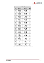
Table 2-2: P3 PMC Connector Pin Definitions
Jn1 (32 Bit)
Jn2 (32Bit)
Pin
Signal
Signal
Pin Pin
Signal
Signal
Pin
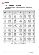
Table 2-1: P1 and P2 PMC Connector Pin Definitions
Содержание cPCI-8301
Страница 4: ......
Страница 8: ...iv...
Страница 11: ...Introduction 3 1 3 cPCI 8301 Mechanical Drawing Figure 1 1 cPCI 8301 Carrier Board Layout...
Страница 14: ...6 Introduction...
Страница 20: ...12 Connectors...


