


Industrial
Electronic Devices
ADFweb.com Srl – IT31010 – Mareno – Treviso INFO:
www.adfweb.com
Phone +39.0438.30.91.31
User Manual
OPC UA Client / CAN
Document code: MN67B12_ENG Revision 1.000 Page 23 of 32
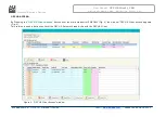
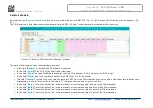
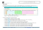
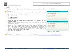
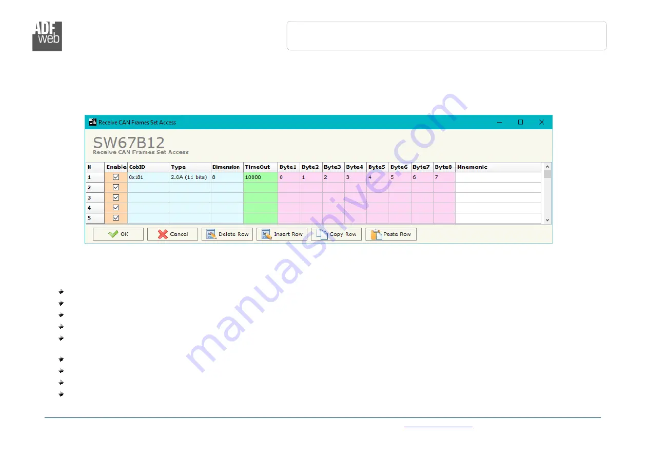
RECEIVE FRAMES:
By pressing the “
Receive Frames
” button from the main window for SW67B12 (Fig. 2) the “Receive CAN Frames” window appears (Fig.
10).
The COB inserted in this table contains the data to write on OPC UA side. These frames are accepted by the converter.
The data of the columns have the following meanings:
If the field “
Enable
” is checked, the CAN frame is enabled;
In the field “
Cob-ID
” the COB of the CAN frame is defined;
In the field “
Type
” the type of CAN packet use for the Cob-ID is defined (2.0A (11 bits) or 2.0B (29 bits));
In the field “
Dimension
” the number of byte of the COB (from 1 to 8) is defined;
The field “
TimeOut
” is used for put at zero the data into OPC UA if the CAN frame doesn’t arrive with a frequency less than the time
expressed in the field. If the value in the field is ‘0’, it means that you don’t want to use this;
In the field “
Byte1
” insert the byte of the internal memory array where saving 1st byte of the CAN message;
In the field “
Byte2
” insert the byte of the internal memory array where saving 2nd byte of the CAN message;
In the field “
Byte3
” insert the byte of the internal memory array where saving 3rd byte of the CAN message;
In the field “
Byte4
” insert the byte of the internal memory array where saving 4th byte of the CAN message;
Figure 10: “Receive CAN Frames Set Access” window


