background image

Chapter 4 - Installation for AdeptSix Robots

38

Adept PA-4 Power Chassis User’s Guide, Rev E

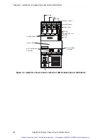
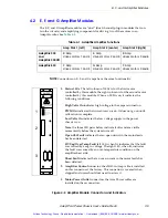
Figure 4-1. Adept PA-4 Power Chassis with sMAI Module

The sMAI, as with all of Adept's distributed-control products, is connected to a host 
Adept SmartController via the SmartServo interface (based on IEEE 1394).

The PA-4 CAT-3 features:

• AC-DC power conversion for amplifier modules

• Multiple amplifier/module support (4 slots)

• EN-954 Category 3-compliant E-Stop contactors

The sMAI module features: 

• RISC microprocessor for servo loop control

• Interfaces to 6 axes of Adept power amplifiers

• Interfaces to robust digital serial absolute encoders

• Interfaces to 6 axes of electromechanical brakes

• Redundant E-Stop and teach mode safety circuits

• Smartservo (IEEE-1394) interface for distributed control

See 

page 40

 for a description of the connectors and indicators on the sMAI.

adept 
technolo

g

y, inc.

LOW VOLTS ON

HV SAG/OVER TEMP FAULT

DO NOT REMOVE OR INSTALL THIS

SHORT FAULT

OPEN CKT FAULT

MODULE UNLESS HI

G

H VOLTS LED

IS COMPLETELY DISTIN

G

UISHED

PWM ON

CH1

HIGH VOLTS ON

CH2

A
M
P
L
I
F
I
E
R

C
O
N
T
R
O
L

CH2

CH1

M
O
T
O
R

P
O
W
E
R

O
U
T
P
U
T

DUAL E AMP

LOW VOLTS ON

HV SAG/OVER TEMP FAULT

DO NOT REMOVE OR INSTALL THIS

SHORT FAULT

OPEN CKT FAULT

MODULE UNLESS HI

G

H VOLTS LED

IS COMPLETELY DISTIN

G

UISHED

PWM ON

CH1

HIGH VOLTS ON

CH2

A
M
P
L
I
F
I
E
R

C
O
N
T
R
O
L

CH2

CH1

M
O
T
O
R

P
O
W
E
R

O
U
T
P
U
T

DUAL E AMP

DO NO

IS CO

CH1 C

M
O
T
O
R

P
O
W
E
R

O
U
T
P
U
T

DU

Dual E Amp #1

Dual E Amp #2

Dual E Amp #3

sMAI Module

®

Artisan Technology Group - Quality Instrumentation ... Guaranteed | (888) 88-SOURCE | www.artisantg.com

Содержание PA-4 CAT-3

Страница 1: ...underutilized and idle equipment along with credit for buybacks and trade ins Custom engineering so your equipment works exactly as you specify Critical and expedited services Leasing Rentals Demos In...

Страница 2: ...E R C O N T R O L CH2 CH1 M O T O R P O W E R O U T P U T J AMP J AMP J AMP LOW VOLTS ON HV SAG OVER TEMP FAULT DO NOT REMOVE OR INSTALL THIS SHORT FAULT OPEN CKT FAULT MODULE UNLESS HIGH VOLTS LED IS...

Страница 3: ...Artisan Technology Group Quality Instrumentation Guaranteed 888 88 SOURCE www artisantg com...

Страница 4: ...OT REMOVE OR INSTALL THIS SHORT FAULT OPEN CKT FAULT MODULE UNLESS HIGH VOLTS LED IS COMPLETELY DISTINGUISHED PWM ON CH1 HIGH VOLTS ON CH2 CH2 CH1 M O T O R P O W E R O U T P U T LOW VOLTS ON HV SAG O...

Страница 5: ...Top Adept FFE Adept FlexFeeder 250 Adept IC Adept iSight Adept Impulse Feeder Adept LineVision Adept MB 10 ServoKit Adept MC Adept MotionBlox 10 Adept MotionBlox 40L Adept MotionBlox 40R Adept MV Adep...

Страница 6: ...ssis 19 2 1 Space Around the Chassis 19 2 2 Panel or Rack Mounting 20 Panel Mounting 20 Rack Mounting 20 2 3 Adept PA 4 Dimensions 22 3 Installation for Adept Viper and Cobra s850 Robots 25 3 1 Overvi...

Страница 7: ...Installing Amplifier and Control Modules 48 Removing Amplifier Modules 49 Installing Amplifier Modules 49 6 4 PA 4 CAT 3 Power Chassis LED Functions 50 6 5 Changing the Power Chassis Voltage Setting...

Страница 8: ...HP Module Viper s1700 Robots 29 Figure 3 5 J Amplifier Module Connectors and Indicators 31 Figure 3 6 sDAI Module Connectors and Indicators 32 Figure 3 7 External Brake Connector Pinouts 34 Figure 3...

Страница 9: ...List of Figures 8 Adept PA 4 Power Chassis User s Guide Rev E Artisan Technology Group Quality Instrumentation Guaranteed 888 88 SOURCE www artisantg com...

Страница 10: ...ION HIGH VOLTAGE INSIDE B R A K E STATUS SmartServo 1 2 R S 2 3 2 E X P I O X S L V C N P G 1 2 3 C N P G 4 5 6 C N 2 5 C N 2 9 DAI s adept technology inc LOW VOLTS ON HV SAG OVER TEMP FAULT DO NOT RE...

Страница 11: ...ng Altitude up to 2000 m 6500 ft Pollution degree 2 IEC 1131 2 EN 61131 2 Free space around power chassis for proper cooling 50 mm 2 inches in front 25 mm 1 inch at top Power chassis subassembly prote...

Страница 12: ...ee Figure 1 2 on the lower right side of the PA 4 front panel there are additional labels for diagnostic LEDs See Figure 6 1 on page 50 This new PA 4 is also backwards compatible with earlier Adept sy...

Страница 13: ...contain the circuitry and amplifying components for driving two motors H and I Amps Adept Viper s1700 robot systems J Amp Adept Viper s650 s850 and Adept Viper s1300 robot systems K Amp Adept Viper s...

Страница 14: ...stallation and operation of the Adept Viper s650 s850 Adept Viper s1300 and Adept Viper s1700 robots Adept Cobra s850 Robot User s Guide Adept Cobra s850 Inverted Robot User s Guide Contains complete...

Страница 15: ...VAC or 380 415 VAC You must be very careful when installing and operating these products Read and understand the Safety chapter in your robot manual before attempting to install these products Observ...

Страница 16: ...equirements published by the Robotic Industries Association RIA in conjunction with the American National Standards Institute The publication ANSI RIA R15 06 contains guidelines for robot system insta...

Страница 17: ...Kingdom Phone 44 0 20 8996 9000 Fax 44 0 20 8996 7400 http www bsi global com Document Center Inc 1504 Industrial Way Unit 9 Belmont CA 94002 USA Phone 415 591 7600 Fax 415 591 7617 http www document...

Страница 18: ...ries Inc 333 Pfingsten Road Northbrook IL 60062 2096 USA Phone 1 847 272 8800 Fax 1 847 272 8129 http www ul com Table 1 4 Sources for International Standards and Directives Continued Artisan Technolo...

Страница 19: ...Chapter 1 Introduction 18 Adept PA 4 Power Chassis User s Guide Rev E Artisan Technology Group Quality Instrumentation Guaranteed 888 88 SOURCE www artisantg com...

Страница 20: ...tandards such as OSHA Lockout Tagout USA IEC 204 1 EN 60204 1 2 1 Space Around the Chassis When the PA 4 chassis is installed you must allow 50 mm 2 in at the front of the chassis and 25 mm 1 in at th...

Страница 21: ...ackets screws and washers to rack mount the PA 4 chassis in a standard 19 inch equipment rack You must build an extender panel and attach it to the mounting brackets The brackets can be installed in t...

Страница 22: ...m pan head screw 2 places M4 x 10 mm pan head screw Rack Mount Flush Rack Mount Set Back Panel Mount To Install Mounting Brackets on Adept PA 4 Power Chassis Remove and discard 3 existing countersunk...

Страница 23: ...imensions Figure 2 2 Adept PA 4 Power Chassis Dimensions for Adept Viper and Cobra s850 Robots WARNING Do not turn on AC power to the PA 4 until you have completed installation of the robot controller...

Страница 24: ...ic Adept PA 4 Power Chassis Dimensions Without Modules 216 mm 8 5 in 290 mm 11 4 in 479 mm 18 9 in Front View Side View Top View 136 mm 5 4 in 18 mm 0 7 in adept technology inc 290 mm 11 4 in Artisan...

Страница 25: ...35 mm 5 25 in 146 05 mm 5 75 in 133 35 mm 5 25 in 33 1 mm 1 30 in 8 56 mm 0 34 in 10 3 mm 0 41 in 4x 6 8 mm 0 27 in 4x 22 2 mm 0 87 in 3 2 mm 0 13 in 479 mm 18 8 in 266 mm 10 47 in PA 4 Power Chassis...

Страница 26: ...s Viper s1300 J and K amps Viper s650 s850 J amps Cobra s850 L amps The amplifiers in the Adept Viper robot system are controlled by an sDAI distributed control module The sDAI module resides in the P...

Страница 27: ...L I F I E R C O N T R O L CH2 CH1 M O T O R P O W E R O U T P U T J AMP J AMP J AMP LOW VOLTS ON HV SAG OVER TEMP FAULT DO NOT REMOVE OR INSTALL THIS SHORT FAULT OPEN CKT FAULT MODULE UNLESS HIGH VOL...

Страница 28: ...GH VOLTS ON CH2 A M P L I F I E R C O N T R O L CH2 CH1 M O T O R P O W E R O U T P U T L AMP L AMP LOW VOLTS ON HV SAG OVER TEMP FAULT DO NOT REMOVE OR INSTALL THIS SHORT FAULT OPEN CKT FAULT MODULE...

Страница 29: ...CH1 M O T O R P O W E R O U T P U T K AMP K AMP J AMP LOW VOLTS ON HV SAG OVER TEMP FAULT DO NOT REMOVE OR INSTALL THIS SHORT FAULT OPEN CKT FAULT MODULE UNLESS HIGH VOLTS LED IS COMPLETELY DISTINGUI...

Страница 30: ...G 1 2 3 C N P G 4 5 6 C N 2 5 C N 2 9 DAI s adept technology inc LOW VOLTS ON HV SAG OVER TEMP FAULT DO NOT REMOVE OR INSTALL THIS SHORT FAULT OPEN CKT FAULT MODULE UNLESS HIGH VOLTS LED IS COMPLETELY...

Страница 31: ...n an Adept Viper s1300 robot See Table 3 1 The L Amplifier modules are dual dual channel plug in modules that contain the cir cuitry and amplifying components for driving two of the motors in an Adept...

Страница 32: ...at an open circuit in the motor leads has been detected HV Sag Over Temp Fault left LED when lit indicates that the fault was caused by a sag in voltage The right LED when lit indicates the fault was...

Страница 33: ...eed to access it 4 CNPG123 connector the CNPG123 plug on the Interface Box wire harness is installed on this connector Provides an interface for the respective joint position encoders 5 CN25 connector...

Страница 34: ...ncoder Joint MA Manual Mode hV High Voltage Bus Fault 24 24 V Supply Fault I Initialization Stage Step A Amp Fault Joint M Motor Stalled Joint B IO Blox Fault Address NV Non Volatile Memory AC AC Powe...

Страница 35: ...or carries encoder feedback connections External Brake Connector The External Brake connector s wire list and pinouts are shown below See Figure 3 1 on page 26 for the connector s location This connec...

Страница 36: ...A 4 power chassis and the SmartController 2 Loosen the 3 latching screws at the top of the Interface Box See Figure 3 1 on page 26 3 Lift the Interface Box up slightly and tilt it down Be careful to a...

Страница 37: ...Chapter 3 Installation for Adept Viper and Cobra s850 Robots 36 Adept PA 4 Power Chassis User s Guide Rev E Artisan Technology Group Quality Instrumentation Guaranteed 888 88 SOURCE www artisantg com...

Страница 38: ...h the sMAI smart Multi Axis Interface module meet the Category 3 E Stop requirements per EN 954 The PA 4 can be configured with E F and G amplifier modules to support the AdeptSix robot systems See Se...

Страница 39: ...ach mode safety circuits Smartservo IEEE 1394 interface for distributed control See page 40 for a description of the connectors and indicators on the sMAI adept technology inc LOW VOLTS ON HV SAG OVER...

Страница 40: ...s on It does not go on until calibration is complete Low Volts On indicates the low voltage supply in the power chassis is on Note the three LED pairs below indicate faults and are visible momentarily...

Страница 41: ...tion encoders 5 CN25 connector for AdeptSix 600 robots only the CN25 cable from the Arm Signal cable is installed on this connector 6 CN29 connector the CN29 cable from the Arm Power cable is installe...

Страница 42: ...ncoder Joint MA Manual Mode hV High Voltage Bus Fault 24 24 V Supply Fault I Initialization Stage Step A Amp Fault Joint M Motor Stalled Joint B IO Blox Fault Address NV Non Volatile Memory AC AC Powe...

Страница 43: ...Chapter 4 Installation for AdeptSix Robots 42 Adept PA 4 Power Chassis User s Guide Rev E Artisan Technology Group Quality Instrumentation Guaranteed 888 88 SOURCE www artisantg com...

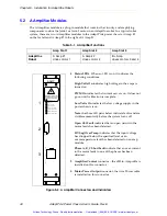
Страница 44: ...INGUISHED PWM ON LOW VOLTS ON OPEN CKT FAULT HV SAG OVER TEMP HIGH VOLTS ON A PHASE SHORT FAULT B PHASE SHORT FAULT C PHASE SHORT FAULT C O N T R O L S I G N A L A AMP M O T O R P O W E R O U T P U T...

Страница 45: ...On indicates the low voltage supply in the power chassis is on Note the three LED pairs below indicate faults and are visible momentarily before the system turns off Open Ckt Fault indicates that an o...

Страница 46: ...that an open circuit in the motor leads has been detected HV Sag Over Temp indicates that either the input voltage has dropped below the specified level or an over temperature fault has been detected...

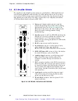
Страница 47: ...ontroller 3 RS 232 connector reserved for future use 4 Teach Restrict connector used for optional CAT 3 safety installations When used the Teach Restrict to B Amp cable is installed on this connector...

Страница 48: ...unauthorized return to service 2 Open the front grill by loosening two screws and swinging the grill out 3 Pull the air filter out and inspect it for dust or dirt particles If cleaning is required use...

Страница 49: ...s used with an Adept Viper or Cobra robot system see Section 3 5 on page 35 for information on removing the interface box The Adept PA 4 power chassis ships from the factory with the amplifier modules...

Страница 50: ...e of the module is flush with the other modules 5 Do not use excessive pressure or force to engage the connector If the board does not properly connect with the rear power connector remove the module...

Страница 51: ...nt 3 Red SC LS This FAULT LED lights when the lower right mounting screw in any of the four slots is loose The fault will reset when the screws are tightened 4 Red K1 K2 F This FAULT LED lights when a...

Страница 52: ...nk tubing one 7 mm 1 4 inch in diameter the other 19 mm 3 4 inch 4 Place the 7 mm 1 4 inch shrink tubing over the end of the blue wire in the power cord and use a heat gun to apply it 5 Fold the blue...

Страница 53: ...ed setting is shown and re install it See Figure 6 3 3 Close the grill and secure the two screws 4 Clearly mark or alter the ID label which is located on the side of the PA 4 chassis to show the new v...

Страница 54: ...of this procedure 2 If installed remove the 4 wire plug 3 Remove and discard the 19 mm 3 4 inch shrink tubing from the end of the power cord 4 Remove and discard the 7 mm 1 4 inch shrink tubing from t...

Страница 55: ...ser s Guide Rev E Figure 6 4 Removing Insulation from Blue Wire in Power Cord 380 415 VAC 19 mm 3 4 inch shrink tubing blue wire power cord from power chassis Artisan Technology Group Quality Instrume...

Страница 56: ...I 40 Customer Service assistance 13 D Dimensions PA 4 mounting brackets 23 PA 4 power chassis 23 Document Library CD ROM 13 14 E E amplifier modules connections indicators 39 functions in AdeptSix rob...

Страница 57: ...y information for plug in modules 12 identification methods 11 LED functions 50 product ID label 11 PA 4 power chassis air filter inspection and cleaning 47 changing voltage setting From 200 240 VAC t...

Страница 58: ...ew 38 Sources for international standards and directives 16 Space around the chassis 19 Status LEDs A amps 44 B amps 45 E amps 39 F amps 39 G amps 39 H amps 31 I amps 31 J amps 31 K amps 31 L amps 31...

Страница 59: ...Index 58 Adept PA 4 Power Chassis User s Guide Rev E Artisan Technology Group Quality Instrumentation Guaranteed 888 88 SOURCE www artisantg com...

Страница 60: ...Artisan Technology Group Quality Instrumentation Guaranteed 888 88 SOURCE www artisantg com...

Страница 61: ...3011 Triad Drive Livermore CA 94551 925 245 3400 P N 02725 000 Rev F Artisan Technology Group Quality Instrumentation Guaranteed 888 88 SOURCE www artisantg com...

Страница 62: ...uipment Have surplus equipment taking up shelf space We ll give it a new home Learn more Visit us at artisantg com for more info on price quotes drivers technical specifications manuals and documentat...

Отзывы: