adept technology Cobra s800 Скачать руководство пользователя страница 63

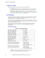
Using Digital I/O on Robot XIO Connector

Adept Cobra s800 Inverted Robot User’s Guide, Rev C 

63

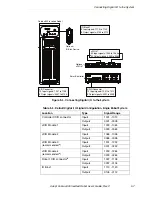
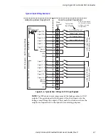
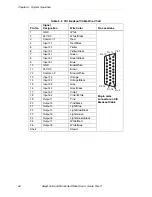
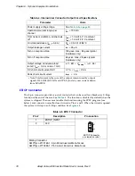
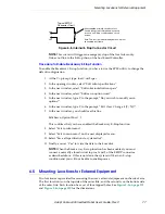
Typical Output Wiring Example

Figure 5-5. Typical User Wiring for XIO Output Signals
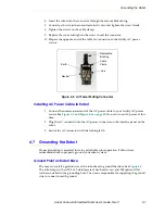
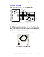
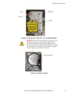
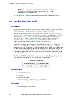
XIO Breakout Cable 

The XIO Breakout cable is available as an option - see 

Figure 5-6

. This cable connects to 

the XIO connector on the robot, and provides flying leads on the user’s end for connecting 
input and output signals in the workcell. The part number for the cable is 04465-000, and 
the length is 5 M (16.4 ft).

See 

Table 5-9 on page 64

 for the wire chart on the cable.

NOTE: 

This cable is not compatible with the XIO Termination Block.

Figure 5-6. Optional XIO Breakout Cable

M

Adept-

Su

pplied E

qu

ipment

U

s

er-

Su

pplied E

qu

ipment

O

u

tp

u

t

s

 1-

8

Typic

a

l U

s

er Lo

a

d

s

XIO Connector – 26-Pin F

em

a

le D-

Sub

+24 VDC

1

9

S

ign

a

l 00

9

7

20

S

ign

a

l 00

98

21

S

ign

a

l 00

99

22

S

ign

a

l 0100

2

3

S

ign

a

l 0101

24

S

ign

a

l 0102

25

S

ign

a

l 010

3

26

S

ign

a

l 0104

GND

GND

Lo

a

d

1

C

us

tomer

AC Power 

Su

pply

10

M

Lo

a

d

Lo

a

d

L

N

(e

qu

iv

a

lent 

circ

u

it)

Wiring
Termin

a

Block

Содержание Cobra s800

Страница 1: ...Adept Cobra s800 Inverted Robot User s Guide...

Страница 2: ......

Страница 3: ...il 2008 3011 Triad Drive Livermore CA 94551 USA Phone 925 245 3400 Fax 925 960 0452 Otto Hahn Strasse 23 44227 Dortmund Germany Phone 49 231 75 89 40 Fax 49 231 75 89 450 151 Lorong Chuan 04 07 New Te...

Страница 4: ...Smart600 Adept Cobra Smart800 Adept DeskTop Adept FFE Adept FlexFeeder 250 Adept IC Adept iSight Adept Impulse Feeder Adept LineVision Adept MB 10 ServoKit Adept MC Adept MotionBlox 10 Adept MotionBlo...

Страница 5: ...the Robot 22 2 3 Precautions and Required Safeguards 23 Safety Barriers 24 Impact and Trapping Points 24 Instructions for Emergency Movement without Drive Power 24 Emergency Recovery Procedures 24 Add...

Страница 6: ...ng Surface 37 Mounting Procedure 38 3 6 Connectors on Robot Interface Panel 40 4 System Installation 43 4 1 System Cable Diagram 43 4 2 Cable and Parts List 44 4 3 Installing the SmartController 44 4...

Страница 7: ...ioning the System 65 Verifying Installation 65 Mechanical Checks 65 System Cable Checks 65 User Supplied Safety Equipment Checks 66 System Start up Procedure 66 Verifying E Stop Functions 67 Verify Ro...

Страница 8: ...tstop Locations for Joint 2 91 7 IP 65 Option 95 7 1 IEC IP 65 Classification 95 7 2 Modifications to Meet IP 65 Classification 96 Outer link 96 AIB Cable Seal 96 Controller 96 Hard Stop Rotation Rang...

Страница 9: ...e Encoder Battery 122 Battery Replacement Time Periods 122 Battery Replacement Procedure 122 Installing the Encoder Battery in the Inner Link 123 9 Technical Specifications 125 9 1 Dimension Drawings...

Страница 10: ...0 Inverted Robot User s Guide Rev C 10 6 System Startup Procedure 147 10 7 Operating with an Adept Pendant 148 10 8 Programming Information 148 V Language Programming 148 V Monitor Commands 148 10 9 E...

Страница 11: ...Ground Point on Robot Base standard robot shown 52 Figure 5 1 Robot Status LED Indicator Location 53 Figure 5 2 Status Panel 54 Figure 5 3 Connecting Digital I O to the System 57 Figure 5 4 Typical U...

Страница 12: ...th Outer Link Cover Removed 102 Figure 7 7 IP 65 Tool Flange 103 Figure 7 8 Compressed Air Fitting on Robot 104 Figure 7 9 User Connectors on Robot Base capped covered 105 Figure 7 10 IP 65 Internal C...

Страница 13: ...Robot System Cable Diagram 137 Figure 10 2 Digital I O Connections to a Dual Robot System 139 Figure 10 3 Input Output Block Configuration in Dual Robot Systems 142 Figure 10 4 Input Output Block Conf...

Страница 14: ......

Страница 15: ...4 are rotational Joint 3 is translational See Figure 1 2 on page 16 for a description of the robot joint locations The Adept Cobra s800 Inverted robots require an Adept SmartController The robots are...

Страница 16: ...and full servo control Adept SmartAmp AIB features On board digital I O Low EMI for use with noise sensitive equipment No external fan for quiet robot operation 8 kHz servo rate delivers low positiona...

Страница 17: ...Viper s series robots Adept Python linear modules Adept MotionBlox 10 Adept sMI6 SmartMotion The SmartController CX supports an integrated vision option and a conveyor tracking option as well as othe...

Страница 18: ...4 Create a 24 VDC cable and connect it between the robot and the user supplied 24 VDC power supply See Section 4 5 on page 45 5 Create a 200 240 VAC cable and connect it between the robot and the fac...

Страница 19: ...he system reconfiguring installed components and adding other optional components see Table 1 2 These manuals are available on the Adept Document Library CD ROM shipped with each system Table 1 2 Rela...

Страница 20: ...system the separate ADL CD shipped with your system the Adept Web site Select Document Library from the Adept home page To go directly to the Adept Document Library type the following URL into your br...

Страница 21: ...dous electrical situation which if not avoided will result in death or serious injury DANGER This indicates an imminently hazardous situation which if not avoided will result in death or serious injur...

Страница 22: ...s Guide Rev C 2 2 Warning Labels on the Robot Figure 2 1 and Figure 2 2 show the warning labels on the Adept Cobra s series robots Figure 2 1 Electrical and Thermal Warning Labels on AIB Chassis Figu...

Страница 23: ...bove Do not remove the J3 ENC or J4 ENC encoder cable connectors from their sockets If they are removed the calibration data will be lost and the robot must be run through a factory recalibration proc...

Страница 24: ...ch the danger zone of the robot The Adept control system has features that aid the user in constructing system safeguards including customer emergency stop circuitry and digital input and output lines...

Страница 25: ...ansi org Underwriters Laboratories Inc 333 Pfingsten Road Northbrook IL 60062 2096 USA Phone 1 847 272 8800 Fax 1 847 272 8129 http www ul com info standard htm BSI Group British Standards 389 Chiswi...

Страница 26: ...ct based on the intended applications of the robot The conclusions are summarized following DIN Deutsches Institut f r Normung e V German Institute for Standardization Burggrafenstrasse 6 10787 Berlin...

Страница 27: ...1 See Figure 9 9 on page 132 for an E stop internal circuit diagram Slow Speed Control Function and Testing Adept robots can also be controlled manually when the operating mode key switch is in the M...

Страница 28: ...218 EN 775 Manipulating Robots Safety In addition a software based reduced speed mode has been incorporated to limit speed and impact forces on the Operator and production tooling when the robot is op...

Страница 29: ...ation ask Adept to determine if it is an intended use or not 2 6 Robot Modifications It is sometimes necessary to modify the robot in order to successfully integrate it into a workcell Unfortunately m...

Страница 30: ...d with the Adept Cobra s series robot grippers conveyor belts etc must not reduce the workcell safeguards All emergency stop switches must always be accessible If the robot is to be used in an EU or E...

Страница 31: ...d and power of the robot is reduced but it could still cause injury to the operator Before performing maintenance in the working envelope of the robot High Power must be switched off and the power sup...

Страница 32: ...s to enable them to avoid the dangers electrical and or mechanical All personnel must observe sound safety practices during the installation operation and testing of all electrically powered equipment...

Страница 33: ...net or use another adequate method to prevent access to them 2 15 Safety Aspects While Performing Maintenance Only skilled persons with the necessary knowledge about safety and operating the equipment...

Страница 34: ...Rev C 2 17 What to Do in an Emergency Situation Press any E Stop button a red push button on a yellow background field and then follow the internal procedures of your company or organization for an em...

Страница 35: ...the package from excessive shock and vibration Use a forklift or pallet jack to transport and store the packaged equipment see Figure 3 1 The robot must always be stored and shipped in an upright pos...

Страница 36: ...y Inspect each item for external damage as it is removed from its container If any damage is evident contact Adept see Section 1 4 on page 19 Retain all containers and packaging materials These items...

Страница 37: ...ad and stiffness The mounting structure must be rigid enough to prevent vibration and flexing during robot operation Excessive vibration or mounting flexure will degrade robot performance Adept recomm...

Страница 38: ...points for user installed dowel pins in the mounting surface Using locating pins can improve the ability to remove and reinstall the robot in the same position Mounting Procedure Always use at least...

Страница 39: ...ll bolted to the transportation pallet use a forklift or other mechanical lifting device to lift the robot and position it directly under the mounting surface Make sure that one person watches the rob...

Страница 40: ...Remove the bolts securing the robot to the pallet Retain these bolts for possible later relocation of the equipment Move the pallet out of the way 7 Tighten the customer supplied mounting bolts to the...

Страница 41: ...for connecting the IEEE 1394 cable from the controller SmartServo Port 1 1 to the robot upper connector SmartServo Port 1 The robot lower connector SmartServo Port 2 can be used to connect to a second...

Страница 42: ......

Страница 43: ...r Supply User Supplied 200 240 VAC single phase Controller XFP to Front Panel XFP Front Panel XSYS Cable Controller XSYS to Robot XSLV 24VDC Power to Controller XDC1 24VDC Power to Robot 24V DC Input...

Страница 44: ...nd 6 Install the AdeptWindows PC user interface Refer to the AdeptWindows Installation Guide Table 4 1 Cable and Parts List Part Description Part Number Notes IEEE 1394 Cable 4 5 M 10410 00545 Standar...

Страница 45: ...commends a 24 V 6 A power supply to allow for startup current draw and load from connected user devices such as solenoids and digital I O loads If multiple robots are to be sourced from a common 24 V...

Страница 46: ...E You also must create a separate 24 VDC cable for the SmartController That cable uses a different style of connector See the Adept SmartController User s Guide 3 Crimp the pins onto the wires using t...

Страница 47: ...or on the interface panel on the back of the robot The cable shield should be connected to the ground point on the interface panel See Figure 4 6 on page 52 Figure 4 2 User Supplied 24 VDC Cable NOTE...

Страница 48: ...ional Electrical Code and any local codes Ensure compliance with all local and national safety and electrical codes for the installation and operation of the robot system Table 4 5 Specifications for...

Страница 49: ...aks may appear on mains power supply lines as a result of power interruptions to high energy equipment such as a blown fuse on one branch in a 3 phase system This will cause high current pulses at rel...

Страница 50: ...r shown in Table 4 7 2 Open the connector by unscrewing the screw on the shell and removing the cover 3 Loosen the two screws on the cable clamp See Figure 4 5 on page 51 4 Use 18 AWG wire to create t...

Страница 51: ...power source See Figure 4 3 and Figure 4 4 on page 50 Do not turn on AC power at this time 2 Plug the AC connector into the AC power connector on the interface panel on the robot 3 Secure the AC conn...

Страница 52: ...point on the tool flange 4 8 Installing User Supplied Safety Equipment The user is responsible for installing safety barriers to protect personnel from coming in contact with the robot unintentionally...

Страница 53: ...tion displayed by this LED Legacy models have a bi color red and green LED See Table 5 2 for the status information displayed by this LED Figure 5 1 Robot Status LED Indicator Location Table 5 1 Statu...

Страница 54: ...l faults are recorded All displayed faults will be cleared from the display and reset to a no fault condition upon successfully enabling high power to the robot or power cycling the 24 V supply to the...

Страница 55: ...t prevent you from moving the robot manually once the robot has stopped and High Power has been removed In addition Joint 3 has an electromechanical brake The brake is released when High Power is enab...

Страница 56: ...he values shown in Figure 5 3 and Table 5 5 on page 57 WARNING Due to the effect of gravity pressing the Brake Release button may cause the quill to fall When the Brake Release button is pressed Joint...

Страница 57: ...08 Outputs 0097 0104 IO Blox 1 Inputs 1113 1120 Outputs 0105 0112 SF IEEE 1394 X2 SC DIO LINK S N 3563 XXXXX X1 24V 0 5A R OK X4 1 1 1 2 XDC1 XDC2 X3 R ON SmartServo IEEE 1394 1 2 3 4 SF ES HD SW1 1 1...

Страница 58: ...puts 1137 1144 Outputs 0129 0136 a For sDIO modules 3 and 4 you must configure the signals using CONFIG_C to have the system support those modules See the Adept SmartController User s Guide for additi...

Страница 59: ...104 Table 5 6 XIO Signal Designations Pin No Designation Signal Bank V Signal Number Pin Locations 1 GND XIO 26 pin female connector on Robot Interface Panel 2 24 VDC 3 Common 1 1 4 Input 1 1 1 1097 5...

Страница 60: ...age 59 or through the optional XIO Termination Block See the documentation supplied with the Termination Block for details The XIO inputs cannot be used for REACTI programming high speed interrupts or...

Страница 61: ...t Supplied Equipment User Supplied Equipment Signal 1097 Part Present Sensor 4 Signal 1098 Feeder Empty Sensor 5 Signal 1099 Part Jammed Sensor 6 Signal 1100 Sealant Ready Sensor 7 Signal 1101 8 Signa...

Страница 62: ...obot through a self resetting polyfuse The outputs are accessed through direct connection to the XIO connector see Table 5 6 on page 59 or through the optional XIO Termination Block See the documentat...

Страница 63: ...als in the workcell The part number for the cable is 04465 000 and the length is 5 M 16 4 ft See Table 5 9 on page 64 for the wire chart on the cable NOTE This cable is not compatible with the XIO Ter...

Страница 64: ...3 1 Yellow Black 7 Input 4 1 Green 8 Input 5 1 Green Black 9 Input 6 1 Blue 10 GND Blue White 11 24 VDC Brown 12 Common 2 Brown White 13 Input 1 2 Orange 14 Input 2 2 Orange Black 15 Input 3 2 Gray 1...

Страница 65: ...the robot is mounted level and that all fasteners are properly installed and tightened Verify that any end of arm tooling is properly installed Verify that all other peripheral equipment is properly i...

Страница 66: ...the D default drive 5 Wait for the system to complete the boot cycle Once completed the system will return with a dot prompt and the following window should be displayed Figure 5 7 Typical Start up S...

Страница 67: ...h Power and then opening the safety device The High Power push button light on the Front Panel should go out Verify Robot Motions Use the pendant to test the motion of each axis on the robot to confir...

Страница 68: ......

Страница 69: ...he outer link and the user flange 6 2 Removing and Installing the User Flange The user flange can be removed and reinstalled If the flange is removed it must be reinstalled in exactly the same positio...

Страница 70: ...from the quill shaft 4 Use a socket driver to tighten one of the socket head screws part of the way then tighten the other one the same amount Alternate between the two screws so there is even pressur...

Страница 71: ...anel IP 65 version The connector covers plugs and caps can be removed from the IP 65 version panel if needed If the connections are not to be used the covers must remain in place User Electrical IO Bl...

Страница 72: ...nector is wired directly to a 25 pin female connector on the top of the outer link see Figure 6 4 These connectors can be used to run user electrical signals from the user panel through the robot and...

Страница 73: ...r WARNING When the outer link cover is removed you see the label shown above Do not remove the J3 ENC or J4 ENC encoder cable connectors from their sockets If they are removed the calibration data wil...

Страница 74: ...noids or other user supplied devices See Table 6 2 and Figure 6 7 on page 75 Table 6 1 SOLND Connector Pinout Pin Description Pin Location 1 Output 3001 SOLND Connector as viewed on robot 2 Ground 3 O...

Страница 75: ...tor Pinout Pin Description Pin Location 1 24 VDC see Table 6 4 for current specs EOAPWR Connector as viewed on robot 2 Ground 3 24 VDC see Table 6 4 for current specs 4 Ground Mating Connector AMP Tyc...

Страница 76: ...range per channel Iout 700 mA Total Current Limitation all channels ona a Note Total current is the sum of the output current used by output signals 3001 3004 SOLND and OP3 4 and any user current dra...

Страница 77: ...ed the Breakaway E Stop function 8 Select Exit to robot menu 9 Select Exit to main menu on the next displayed menu 10 Select Save all specifications to system disk 11 Finally answer Yes to write the d...

Страница 78: ...the SIGNAL command in the V Language Reference Guide for additional information The Adept supplied solenoids each draw a nominal 75 mA from 24 VDC The solenoid valve assembly consists of two independ...

Страница 79: ...ld see Figure 6 9 5 Mount the solenoid manifold onto the bracket using the supplied M3 x 30 mm screws and washers see Figure 6 10 6 Insert the spare air line into the air intake coupling of the soleno...

Страница 80: ...se tie wraps as needed to secure the tubing 11 For the IP 65 version robot skip to Step 16 12 Remove the four screws from the User Connector Panel see Figure 6 3 on page 71 and remove the cover enough...

Страница 81: ...screws to 1 6 N m 14 in lb of torque Refer to Removing Installing Outer Link Cover on page 100 for IP 65 version torque values 17 Connect the factory air supply to the 6 mm User Air connector For the...

Страница 82: ...mera brackets to the camera plate with two stainless steel washers and two M4 x 12 mm screws for each bracket The camera brackets are not required unless you are mounting more than one camera 3 Mount...

Страница 83: ...t the robot base see Figure 6 3 on page 71 A nonstandard DeviceNet cable consisting of two shielded twisted pairs that connect the above connectors Adept considers this cabling to be a drop line with...

Страница 84: ...lling Adjustable Hardstops Adept offers an adjustable hardstop kit for Joint 1 and Joint 2 on the Adept Cobra s800 Inverted and standard robot This is a user installed option that can be used to limit...

Страница 85: ...wrench Tighten to a torque of 5 1 N m 45 in lb 3 Repeat the process on the other side of the robot Modifying Joint Limit Softstop Locations for Joint 1 After installing the adjustable hardstops you mu...

Страница 86: ...enu select Edit joint motion specs See Figure 6 16 Figure 6 16 Robot Specs Menu 4 The system should go to the menu for Joint 1 verify this at the top of the screen as shown in Figure 6 17 If it is not...

Страница 87: ...the lower limit softstop value must be a negative number Figure 6 18 Joint 1 Menu Lower Limit 7 In the next menu select Upper joint limit See Figure 6 19 8 In the next menu enter the new value for th...

Страница 88: ...w joint limits will be in affect when the system reboot is complete Joint 2 Adjustable Hardstops The Joint 2 Adjustable Hardstop Figure 6 20 consists of two curved plates that are the adjustable hards...

Страница 89: ...Installation Procedure 1 Remove the bottom cover from the underside of the inner link 2 For the IP 65 version from the underside of the inner link looking up remove the 12 M5 x 10 screws and lock wash...

Страница 90: ...hers to secure each plate Tighten the screws to a torque of 4 5 N m 40 in lb Joint 2 Adjustable Hardstop Plates Installed in Position 1 12 thru holes for M5 x 10 screws for installing Joint 2 hardstop...

Страница 91: ...5 N m 40 in lb Note that there will be 8 M5 x 10 screws and lock washers from the adjustable hardstop kit left over after the IP 65 installation After this step all 12 holes around Joint 2 should be s...

Страница 92: ...6 on page 86 4 In the next menu select Change joint number and enter 2 for Joint 2 Verify that the screen for configuring Joint 2 is displayed by checking the top of the screen see Figure 6 25 for an...

Страница 93: ...tstops you must save the new values Select Exit then select Save ALL specifications to system disk See Figure 6 15 on page 86 10 Reboot the system by cycling 24 VDC power to the SmartController The ne...

Страница 94: ......

Страница 95: ...P 65 Dust Protection No ingress of dust is allowed Water Resistance protection of the equipment inside the robot shell against harmful effects due to the ingress of water Specifically for IP 65 Water...

Страница 96: ...rd Stop Rotation Range Because the outer link cover has been widened it cannot rotate as far as the standard inverted Cobra The hard stop has been enlarged to limit the outer link s rotation at J2 to...

Страница 97: ...o remove the cables from the AIB or remove the AIB from the robot for any reason please follow the procedures in this section NOTE If you only need to disconnect cables from the AIB you can do so by j...

Страница 98: ...are shown in grey Removing the Cable Entry Housing Cover The cable entry housing cover is attached to the cable entry housing body with four screws The Roxtec cable seal assembly is attached to the c...

Страница 99: ...e cover to the body and carefully lift the cover The gasket between the cover and body is attached to the body with adhesive Leave the gasket in place It will be reused for reassembly The cables will...

Страница 100: ...ing body 1 Remove the four M4 x 50 screws holding the cable entry housing body to the AIB 2 Remove the cable entry housing from the AIB The gasket between the AIB and body is attached to the body with...

Страница 101: ...side of the cover 4 on each side see Figure 7 5 loosen only 1 to 2 turns just enough to loosen the inside clamp nuts Do not completely remove the screws See the label on the side of the outer link cov...

Страница 102: ...hed as the cover presses down to make the seal NOTE As you lower the cover onto the outer link make sure the 8 side screws are pushed all the way in so the clamp nuts will slide into the correct posit...

Страница 103: ...d periodically to make sure these requirements are being met as part of a periodic maintenance program Sealing the Tool Flange The tool flange must be sealed so that the robot shell can be positively...

Страница 104: ...the air fitting The specification for the regulated air supply is shown in Table 7 1 Table 7 1 Compressed Air Specifications Required Air Pressure Required Air Flow Minimum 3 bar 10 44 PSI 10 57 liter...

Страница 105: ...ire a gel seal gasket to maintain an adequate seal The gaskets are supplied in the accessory kit p n 04860 000 Figure 7 9 User Connectors on Robot Base capped covered The user electrical and DeviceNet...

Страница 106: ...periodically for cracks wear or damage Replace bellows if necessary using the following procedure 1 Remove the lower bellows clamp by removing two M3 screws and pulling the clamp apart See Figure 7 11...

Страница 107: ...s seam on both upper and lower clamps 7 9 Installing the Roxtec Cable Seal Assembly NOTE If you only need to disconnect cables from the AIB refer to Section 7 4 on page 97 Figure 7 11 Bellows Figure 7...

Страница 108: ...ded View of Roxtec Assembly 1 Remove the lock nut from the housing 2 Verify that the o ring is positioned correctly 3 Insert the housing into the Cable Entry Housing Cover and fasten with the lock nut...

Страница 109: ...wn in 7 7 There must be a 0 1 1 0 mm gap between the two module halves when held against the cables 8 Thoroughly lubricate all modules both inside and outside with Roxtec Lubricant CAUTION The Roxtec...

Страница 110: ...10 Place the cables into the adapted module 11 Add the second adapted module half on top of the cables and module half 12 Repeat 10 and 11 until the Roxtec frame is filled Use non adapted modules whe...

Страница 111: ...o a torque of 18 24 ft lbs 25 32 N m 7 10 Removing the Roxtec Cable Seal Assembly Removal disassembly of the Roxtec Cable Seal Assembly is the reverse of the Assembly with the following important note...

Страница 112: ......

Страница 113: ...r interlocks 6 months See Section 8 2 Check robot mounting bolts 6 months See Section 8 3 Check for signs of oil around the harmonic drive 3 months See Section 8 4 Lubricate Joint 3 Z axis ball screw...

Страница 114: ...8 3 Checking Robot Mounting Bolts Check the tightness of the base mounting bolts every 6 months Tighten to 85 N m 65 ft lb Also check the tightness of all cover plate screws 8 4 Checking for Oil Arou...

Страница 115: ...grease with a clean lint free soft cloth 6 Apply a thin film of grease to any grooves of the ball screw that you did not reach in step 4 7 Move Joint 3 up and down several times to spread the grease e...

Страница 116: ...crew Lubrication Points NOTE Apply grease to the three vertical grooves and the spiral groove A A Section A A Top View Looking Down Quill Shaft Vertical Groove Lube Point A Vertical Groove Lube Point...

Страница 117: ...nput connector See Figure 3 5 on page 40 for locations of connectors 6 Disconnect the 200 240 VAC supply cable from the chassis AC input connector 7 Disconnect the XSLV cable from the chassis XSLV con...

Страница 118: ...n 07116 000 is provided in the accessory kit Unscrew the plug from the hole in the side of the robot body left side as viewed from the AIB See Figure 8 4 Screw the Support Bolt into the side of the ro...

Страница 119: ...s on AIB Chassis NOTE Use care when disconnecting the AIB cables from the PMAI board in the following steps 15 Disconnect the J1 cable from the J1 connector on the PMAI board by disengaging the securi...

Страница 120: ...nnector on the PMAI board by disengaging the securing latches 19 Disconnect and remove the ground wire from the chassis Keep the screw for reassembly later See Figure 8 7 Figure 8 7 Ground Screw on AI...

Страница 121: ...able to the J11 connector on the PMAI board and engage the securing latches 7 Connect the J1 cable to the J1 connector on the PMAI board and engage the securing latches 8 Connect the white amplifier c...

Страница 122: ...information by installing a backup battery in the inner link see Installing the Encoder Battery in the Inner Link on page 123 Battery Replacement Time Periods If the robot is kept in storage and not...

Страница 123: ...battery cable in the wire bundle inside the robot base 10 Place the new battery next to the original one but do not disconnect the original one 11 Connect the new battery to the connectors on the seco...

Страница 124: ...f all power to the robot 3 Remove 10 screws on the bottom of the inner link cover and remove the inner link cover 4 Locate the battery cable in the wire bundle in the inner link Figure 8 10 Location o...

Страница 125: ...pt Cobra s800 Inverted Robot User s Guide Rev C 125 Technical Specifications 9 9 1 Dimension Drawings Figure 9 1 Top and Side Dimensions 160 0 189 160 80 800 0 425 171 5 278 5 32 5 18 0 571 570 729 0...

Страница 126: ...ted Robot User s Guide Rev C Figure 9 2 IP 65 Top and Side Dimensions Other dimensions for the IP 65 version are the same as shown in Figure 9 1 Required clearance to open AIB with the IP 65 connector...

Страница 127: ...Dimension Drawings Adept Cobra s800 Inverted Robot User s Guide Rev C 127 Figure 9 3 Dimensions of the Camera Bracket Mounting Pattern 4X M4x0 7 6H 10 45 3 0 54 10 10 03 7 2X...

Страница 128: ...4X M6 x 1 6 H Thru User Ground See Detail A Detail A 6 80 mm 0 268 in 1 5 mm 0 059 in 4 14 mm 0 163 in 12 0 mm 0 47 in 20 0 mm 0 79 in 3 0 mm 0 12 in 43 mm 1 69 in 30 25 45 41 15 mm 63 0 mm 2 48 in D...

Страница 129: ...Dimension Drawings Adept Cobra s800 Inverted Robot User s Guide Rev C 129 Figure 9 5 External Tooling on Top of Robot Arm 80 A 105 0 DETAIL A 160 0 160 171 5 278 5 425 800 0 189 60 0...

Страница 130: ...Chapter 9 Technical Specifications 130 Adept Cobra s800 Inverted Robot User s Guide Rev C Figure 9 6 External Tooling on Underside of Outer Link Outer Link Bottom View 135 4X M4x0 7 6H 90 8 34...

Страница 131: ...n Max Intrusion Contact Radius R 847 3 mm 33 36 in Minimum Radial Reach R 167 0 mm 6 58 in Cartesian Limits 314 0 mm 12 36 in 387 6 mm 15 26 in 338 0 mm 13 31 in 123 5 123 5 156 5 156 5 Max Instrusion...

Страница 132: ...nternal E STOP Connections Diagram Cobra s600 s800 Internal Connections SmartController Connections Force Guided Relay Cyclic Check Control Circuit Force Guided Force Guided Single Phase AC Input 200...

Страница 133: ...round XSLV1 2 Connector as viewed on Cobra 2 MAN1 ESTOP Manual Input Ch 1 3 MAN2 ESTOP Manual Input Ch 2 4 HIPWRDIS High Power Disable 5 ESTOP_RESET Normally Closed Check Contacts 6 AUTO1 ESTOP Auto I...

Страница 134: ...eral Side Push Force Burst 133 N 30 lb maximum Adept Cycle Burst no J4 rotation b 0 kg 0 48 2 kg 0 54 5 5 kg 0 64 Adept Cycle Burst 180 J4 rotation 0 kg 0 48 2 kg 0 54 5 5 kg 0 76 Adept Cycle Sustaine...

Страница 135: ...airs DeviceNet pass through one available Weight without options 51 kg 112 lb a Specifications subject to change without notice b The robot tool performs continuous path straight line motions 25 mm 1...

Страница 136: ......

Страница 137: ...Adept Cobra s800 Inverted Robot 2 User Supplied 24VDC Power Supply User Supplied 200 240 VAC single phase User Supplied 200 240 VAC single phase Controller XFP to Front Panel XFP Front Panel XSYS Cab...

Страница 138: ...t the factory 2 Use the CONFIG_C utility to determine if the Cobra s800 Inverted robot device modules are already installed in the V system If not use the CONFIG_C utility to load the ASN device modul...

Страница 139: ...EEE 1394 X2 SC DIO LINK S N 3563 XXXXX X1 24V 0 5A R OK X4 1 1 1 2 XDC1 XDC2 X3 R ON SmartServo IEEE 1394 1 2 3 4 SF ES HD SW1 1 1 1 2 2 1 2 2 OK 1 2 3 XDIO LAN HPE OFF XSYS CAMERA Eth 10 100 XUSR Dev...

Страница 140: ...ules See the Adept SmartController User s Guide for additional information on that process Inputs 1201 1232 Outputs 0201 0232 sDIO Module 4 recommended a Inputs 1233 1264 Outputs 0233 0264 Robot 1 XIO...

Страница 141: ...the first output block XIO Inputs XIO inputs are mapped starting at 1097 for robot 1 and 1145 for robot 2 The first 2 bytes are allocated as follows 1st Cobra 1097 1108 on Block 1 2nd Cobra 1145 1156...

Страница 142: ...O Blox 3 IO Blox 4 0121 128 0129 136 Byte 3 Byte 4 IO Blox 1 Byte 1 Byte 2 1113 1120 IO Blox 2 1121 1128 IO Blox 3 IO Blox 4 1129 1136 1137 1144 Byte 3 Byte 4 Input Block 3 ROBOT 2 XIO Input Block 2 B...

Страница 143: ...mmended but must be configured using CONFIG_C so that the system will support those modules 0073 0080 0081 0088 0089 0096 Byte 3 Byte 4 Input Block 17 Byte 1 Byte 2 1065 1072 1073 1080 1081 1088 1089...

Страница 144: ...ingle robots then you will need to go through the configuration process There are two methods for configuring the I O IO configuration by editing system file IO configuration by importing pre configur...

Страница 145: ...ing will be displayed Figure 10 7 System Configuration Editor Menu 4 Configure the I O as shown in Figure 10 8 on page 146 showing an example from a CONFIG_C file look closely at the highlighted areas...

Страница 146: ...IGNAL 1185 INPUT_BLOCK 4 INPUT_BYTE 4 IO_OPTIONAL YES VIS_TRIGGER 1 SIGNAL NONE VIS_TRIGGER 2 SIGNAL NONE DIGITAL_OUTPUT SIGNAL 33 OUTPUT_BLOCK 16 OUTPUT_BYTE 1 IO_OPTIONAL YES SIGNAL 41 OUTPUT_BLOCK...

Страница 147: ...described in the previous section by loading and executing CONFIG_C as shown in IO Configuration by Editing System File on page 144 2 When the screen shown in Figure 10 6 on page 145 is displayed sele...

Страница 148: ...E When using a pendant either the Adept T1 Pendant or the MCP4 with an Adept robot the Free Mode is disabled for safety reasons 10 8 Programming Information V Language Programming By default Task 0 is...

Страница 149: ...most common system messages are described in the V Operating System User s Guide A full list of system messages with complete explanations and suggested user actions is in the V Language Reference Gu...

Страница 150: ......

Страница 151: ...diagram for system 43 camera bracket installation 82 kit 81 circuit protection 24 VDC power 45 47 commissioning system 65 compressed air specifications for IP 65 robot 104 connections user 70 connect...

Страница 152: ...stable for J1 J2 84 93 How Can I Get Help 19 I IEEE 1394 cable 41 44 45 impact and trapping points 24 installation 24 VDC power to robot 45 AC power to robot 51 adjustable hardstops 84 93 camera brack...

Страница 153: ...rvoltage 49 Q qualification of personnel 32 R related manuals 19 repacking for relocation 36 requirements environmental 37 facility 37 operating environment 37 risk assessment 26 RS 232 connector 41 S...

Страница 154: ...cking and inspecting Adept equipment 36 information 36 user air lines 70 air lines in IP 65 robot 105 electrical lines 72 electrical lines in IP 65 robot 105 user flange dimensions 128 installation 69...

Страница 155: ......

Страница 156: ...3011 Triad Drive Livermore CA 94551 925 245 3400 P N 06937 000 Rev C...

Отзывы: