Page 54 of 84
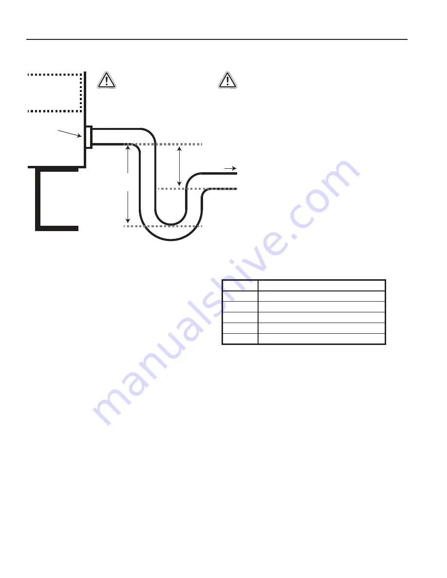
Figure 20: P-Trap Configuration
15.1.2 Condensate Drain
Units are provided with condensate drain connection(s).
Do not operate unit unless a P-Trap is constructed and
attached to drain connection. See Figure 21. Unit must
be level or slightly inclined towards drain. Drain should
pitch down and away from the unit. P-Trap pipe diameter
should be the same as the drain connection diameter.
Units with high internal and external static pressure drops
will require a deeper trap. Prime the trap before operating
the unit.
Drainage of condensate directly onto roof is acceptable if
permitted by local codes. It is recommended that a small
drip pad of either stone, tar, wood or metal be provided to
prevent any possible damage to roof. Refer to local codes
for additional requirements.
15.1.3 Supply and Exhaust Fans
1. Make sure electrical power is isolated.
2. Check power settings for voltage and verify that they
correspond with the data on the motor plate.
3. Check that the motor is grounded (earthed).
4. Check that all electrical leads are sufficiently insulated.
5. Check that all electrical and system connections are
properly made and tightened.
6. Check that all nuts, bolts and setscrews are tightened.
7. Check that the wheel and drive assembly turns freely
without rubbing.
8. Check that drives are tightened, properly aligned
and tensioned.
9. Bump the motor.
10. Check rotation.
15.1.4 Compressors
With the supply fan operational, prepare for
compressor operation.
1. Verify that the crankcase heaters are operating. These
should operate for at least 24 hours before starting the
compressors. Crankcase heaters must be operating
during off cycles to prevent liquid refrigerant from
migrating to the compressor crankcase.
PN: 0527N-0018 Rev.: C
Drain Pan
CAUTION!
Condensate traps must be installed based on the guidelines
below. Units must also be level, or slightly inclined towards
the drain. Failure to follow these guidelines could cause
condensate not to drain properly, and potential intrusion of
water into the space. It is also recommended to pre-prime
traps before initial operation, or long shutdown periods.
B
A
Drain Connection
(Socket or Thread)
A Liquid Seal
Is Required
The Minimum Trap Depth
Should Be Design Based On:
A” = TSP + 1”
B” = A + (A ÷ 2)
Example:
A = 4” + 1”
A = 5”
TSP = Total Static Pressure
(See Work Order or Submittal)
Frame Rail
B = 5 + (5 ÷ 2)
B = 7.5”
Water Flow
Cabinet
Condensate Connection Size
A
3/4”
B
3/4”
C
3/4”
D
1”
E
1”
Table 5: Condensate Connection Sizes
PR Series Installation, Operation, and Maintenance Manual
Содержание PR 036 Series
Страница 2: ...This Page is Intentionally Blank...


