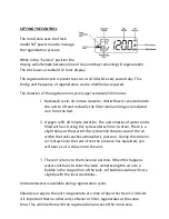
Addie Water Systems IRON GENIE1 Скачать руководство пользователя страница 5


SETTING THE CONTROL 

The Iron Genie uses the Fleck 

model SXT power head to manage 

the regeneration process. 

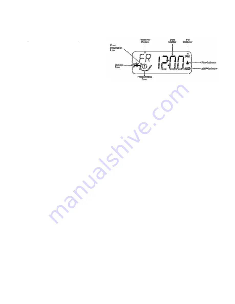
While in the “Service” position the 

display will alternate between time of day and days remaining till regeneration. 

The clock uses a standard 12 hour display. 

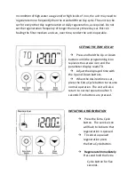
The regeneration cycle is preset to occur at 12:30A.M. every second day. This 

timing and frequency of regeneration can be modified as required. 

The duration of the regeneration cycle is approximately 50 minutes. 

1.


Backwash cycle, 10 minute duration. Water flow is reversed inside 
the unit to lift and reclassify the filter media rinsing accumulated 
iron from the bed. 
 

2.


Oxygen refill, 40 minute duration. The unit empties of water and is 
filled with air. During this cycle water will run to drain. There is a 
slight delay at the start of the cycle while the pressure of the air 
within the tank reaches atmospheric pressure. During this time no 
air is drawn into the tank. Once the pressure has equalized, you 
will hear as air is drawn into the unit. 
 

3.


The unit returns to the In-Service position. When this happens 
water continues to enter the tank, compressing the air into a 
bubble in the top portion of the tank. Air bubble volume will vary 
slightly with the local conditions. 

Untreated water is available during regeneration cycle. 

Should you require the unit to regenerate at a time of day other than 12:30 A.M. 

it is important that no other unit, softener or filter, regenerates at the same 

time. This will interfere with the regeneration process of the Iron Genie. 

Содержание IRON GENIE1

Страница 1: ...IRON GENIE Chemical Free Iron Sulfur Reduction...

Страница 2: ...FLOW RATE GPM PEAK FLOW RATE GPM BACKWASH RATE GPM TIG56SXT SI 10X54 1 0 2 5 3 7 7 0 TIG56SXT SI ECM 13X54 2 0 4 5 7 0 11 0 Peak flow rates are non continuous for residential use only Flow rates are s...

Страница 3: ...r How Does It Work The Iron Genie adds oxygen to the incoming raw water by passing the water through a pressurized air head in the media tank This will begin to convert dissolved elements such as iron...

Страница 4: ...pass position indicated by small pointer on handle Turn on main water supply 5 SLOWLY place the bypass in service position and let water flow into the mineral tank 6 Open the nearest cold water faucet...

Страница 5: ...ion The unit empties of water and is filled with air During this cycle water will run to drain There is a slight delay at the start of the cycle while the pressure of the air within the tank reaches a...

Страница 6: ...s and hold the Up or Down buttons until the programming icon replaces the service icon and the parameter display reads TD Adjust the displayed time with the Up and Down buttons When the desired time i...

Страница 7: ...h and hold the Up and Down Arrow Buttons for 7 seconds Press the Extra Cycle Button once to advance to next parameter 1 DF GAL US Gallon Display Format 2 VT dF1b Down flow Single Backwash 3 CT tc Time...

Страница 8: ...advance on main display If not replace Power Head Assembly Unit does not draw air in BD cycle Injector is plugged Clean or replace injector throat and nozzle Injector screen is plugged Clean or replac...

Страница 9: ...e and system type are set correctly with regard to the unit itself Step the unit through a manual regeneration and verify that it functions correctly If the error re occurs unplug the unit and contact...

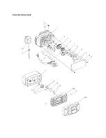
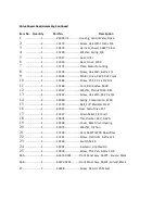
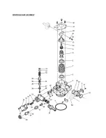
Страница 10: ...Power Head Assembly...

Страница 11: ...lve 5600 12 1 12037 Washer Plain 10 18 8 SS 13 1 40214 Screw Hex Wsh 6 20 x 3 4 14 2 19080 Spring Compression 6700 15 2 13300 Ball 1 4 Stainless Steel 16 1 42933 Gear Main Drive SXT 17 1 13547 Strain...

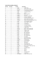
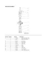
Страница 12: ...CONTROL VALVE ASSEMBLY...

Страница 13: ...2 O ring Brine Spacer 21 1 13303 O ring Injector Cover 22 1 13163 Injector Body 23 1 10913 x Injector Nozzle specify size 24 1 10914 x Injector Throat specify size 25 1 10227 Injector Screen 26 1 1316...

Страница 14: ...o Description 1 1 17290 Bypass Valve Body 3 4 1 13399 Bypass Valve Body 1 2 1 14105 Seal Bypass 3 1 11972 Plug Bypass 4 1 11978 Side Cover 5 1 13604 01 Label 6 8 15727 Screw 7 1 11986 Side Cover 8 1 1...

Страница 15: ...Assembly 13446 41 End Plug Assembly Green 60125 02 Seal and Spacer Kit Low Drive Force 10913 2 Injector Nozzle 2 Blue 10914 2 Injector Throat 2 Blue 10227 Screen 42933 Main Drive Gear 60032 Brine Valv...

Страница 16: ...bypass to the bypass position 2 Relieve the water pressure in the Iron Genie by holding down the Extra Cycle button for 5 seconds Once in the BW cycle pressure will be relieved 3 Push extra cycle butt...

Страница 17: ...alve from injector body 13 Discard o ring at bottom of brine valve hole in injector body 14 Install new o ring at bottom of brine valve hole in injector body 15 Press brine valve into brine valve hole...

Страница 18: ...end of piston rod yoke until piston is out of valve 13 Remove five rubber seals and four plastic spacers from valve body 14 Replace the five rubber seals and four plastic spacers 15 Take the piston a...

Отзывы: