13
INST
ALLA
TION
Transmitter
Remote port
The Remote port has a dual role, it can
either:
• Allow an optional remote control to be
connected to the module, or
• Create an RS232 serial connection with
the receiver module.
When serial devices are attached to the
Remote ports on the transmitter and
receiver modules, the units transparently convey the signals between them at rates up to
115200 baud - no serial configuration is required. An optional serial cable (part number:
VSC50) is available from Adder.
To connect the Remote port
1 Use the optional serial cable (VSC50) to link the Remote port on the rear panel of the
transmitter module with a vacant RS232 serial port on your host computer.
Appendix 1
for pin-out details of the Remote port.
From the serial port of
your host computer
Transmitter
USB links
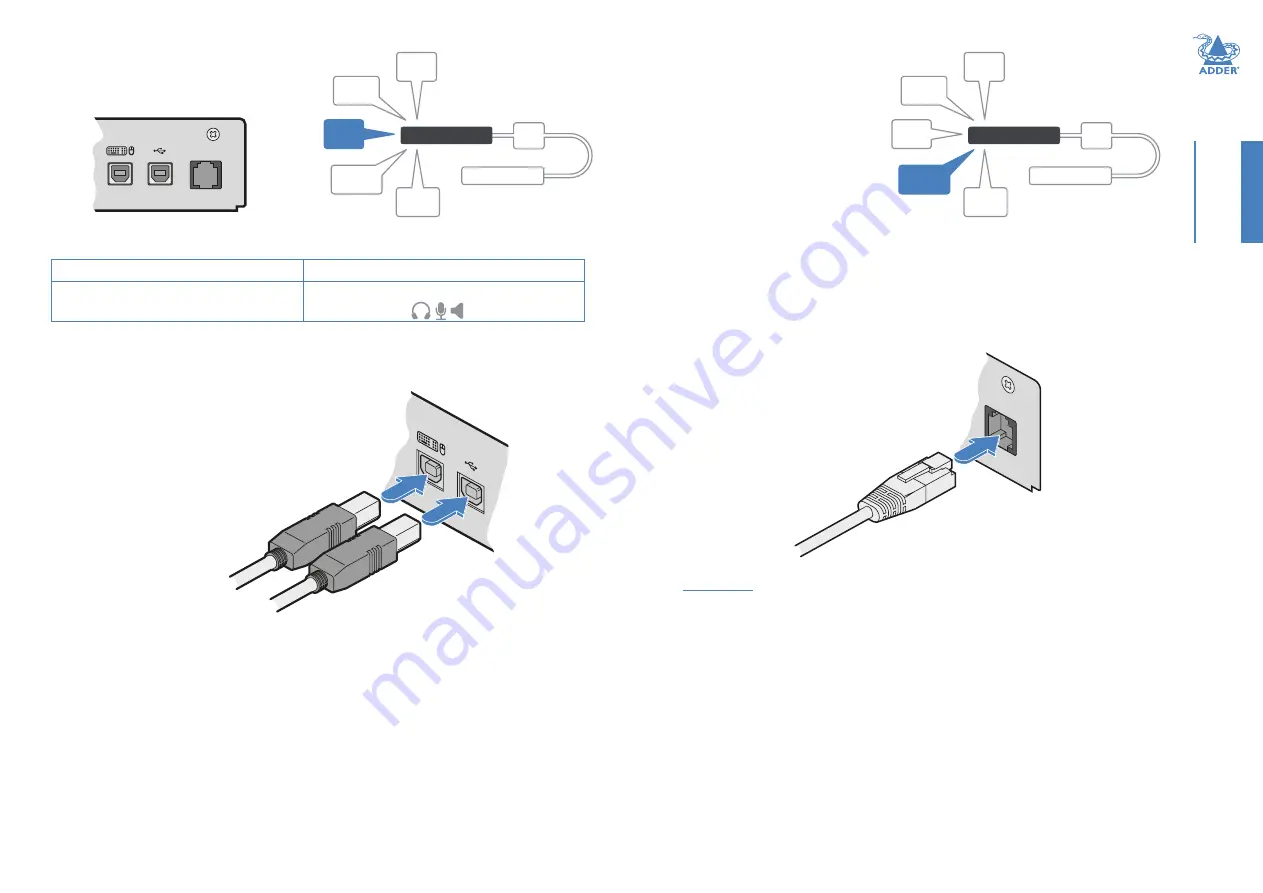
The transmitter module has two USB input
ports on its rear panel:
USB links from the
host computer
RECEIVER
LINK
POWER
IN
VIDEO
LINK(S)
USB
LINK(S)
AUDIO
LINKS
TRANSMITTER
REMOTE
PORT
REMO
TE
RECEIVER
LINK
POWER
IN
VIDEO
LINK(S)
USB
LINK(S)
AUDIO
LINKS
TRANSMITTER
REMOTE
PORT
R
REMOTE
2
1
The ports have different functions:
1
2
USB HID (Human Interface Device)
feed to all USB ports on the receiver
USB audio feed to/from the analog audio
ports labeled
on the receiver
To connect the USB port(s)
1 Connect the type B connector of the
supplied USB/video cable to the left-hand
side USB port (labeled ‘1’ on the diagram
above) on the rear panel of the transmitter
module.
2 Connect the type A connector of the cable to a vacant USB port on the host
computer.
3 Repeat steps 1 and 2 for the second port if USB audio is required (see table above).


