4601 I-V Meter Operation Manual
5.1.3 External Voltage Measurement Terminal
5-3
5.1.3
External Voltage Measurement Terminal
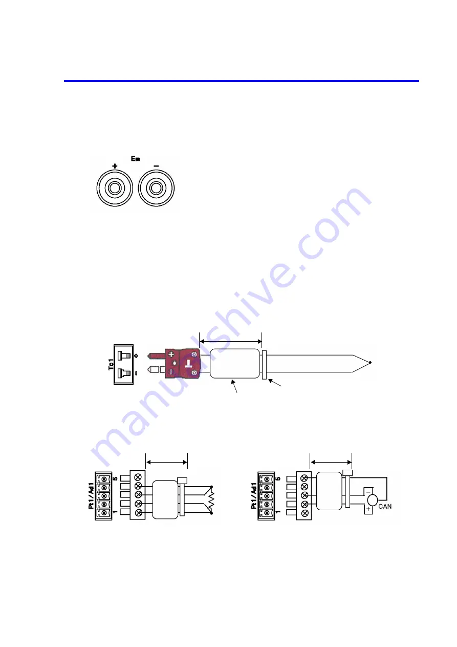
The following figure shows the terminal to measure voltage.
Figure 5-4 External Voltage Measurement Terminal
5.1.4
Temperature Measurement Terminal
Figure 5-5 shows the thermocouple connector and Figure 5-6 shows the connector for the platinum resis-
tance bulb and the IC sensor AD590.
Supplied plugs: JCE-DA0002PX02 and JCS-RB0005JX03 (cover: YEE-1000734) are used.
When connecting a cable to the thermocouple connector Tc1 or Tc2, the platinum resistance bulb connec-
tor Pt1 or Pt2, or the IC sensor connector Ad1 or Ad2, attach the EMC-compliant clamp filter as shown in
Figure 5-5 or Figure 5-6.
Figure 5-5 Thermocouple Connector
Figure 5-6 Platinum Resistance Bulb and IC Sensor Connector
Applicable plug:
Product equivalent to Multi-Contact safety plug
4
Applicable cable:
Cable A01044
Alligator clip adapter A08532
Plug: JCE-DA0002PX02 (Product equivalent to LABFACILITY IM-T-M)
Approx. 45 mm
EMC-compliant clamp filter
Cable tie
(a) Pt Connection
(b) AD590 Connection
Plug: JCS-RB0005JX03, YEE-1000734
(Product equivalent to PHOENIX CONTACT MC1, 5/5-ST-3, 81 or KGG-MC1, 5/5)
Approx.
45 mm
Approx.
45 mm
Содержание 4601 I-V Meter
Страница 2: ......
Страница 8: ......
Страница 14: ......
Страница 18: ......
Страница 70: ...4601 I V Meter Operation Manual 3 4 1 Menu Structure 3 18...
Страница 80: ......
Страница 92: ......
Страница 129: ...4601 I V Meter Operation Manual 5 6 1 Synchronous Operation 5 37...
Страница 146: ......
Страница 182: ......
Страница 230: ......


