


L
OOPBACK
T
ESTING
Initiate loopback testing from the HiGain maintenance menus or use the MODE and SEL
buttons. The inband codes shown below can be sent by a test set.
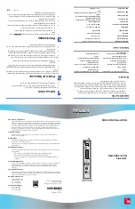
List number (HLU version number)
RS-232 Craft port
Bantam 210 jack provides bidirectional communication
between the unit and an external terminal to allow
configuration and performance monitoring through the
maintenance terminal menus. (Use adapter,
part number 120-1035-01, for jack.)
CLEI code label
M
A
R
G
I
N
(dB)
HLU-388
HiGain HD
L
RS
232
STATUS
SETUP
MODE
SEL
106
105
104
103
102
101
100
DSX-1 RCV
DSX-1 XMT
HDSL 2
HDSL 1
205
204
203
202
201
200
119
118
117
116
115
114
113
112
111
110
Ground
Ground
Frame ground
Fuse alarm*
Ring1
Ring1
Tip1
Tip1
(Mgmt.bus)
Ring
Ring
Tip
Tip
(Factory burn-in)
-48Vdc
219
218
217
216
215
214
213
212
211
210
209
208
207
206
109
108
107
* Fuse alarm is normally floating (0 to 80 Vdc maximum)
and at -48 Vdc (10 mA maximum) when activated.
Four-character display
Displays status, provisioning, and
alarm messages. See tables below
for a list of message descriptions.
Status LED
Reports the following conditions:
Self Test is in process or
a CREM or NLOC loop-
back is in effect
Green LED
Normal operation
Flashing Green LED
HDSL acquisition
Red LED
Fuse alarm
Flashing Red LED
System alarm
Yellow LED
Flashing Yellow LED
Configuration number
System is in ARM mode
System option buttons (for manual setting of
system parameters)
Use MODE and SEL to manually modify user options,
initiate loopbacks, and display DSX-1 line parameters.
1
2
3
4
Press the MODE button for 2 seconds and release.
The front panel alternately displays the first
system parameter and its current setting.
Press SEL to step through all possible system
settings for the displayed parameter.
Press MODE to update the parameter and advance
to the next parameter.
After scrolling through all the parameters, press SEL
to confirm changes when prompted with a CONF YES
message, or press MODE to cancel all changes.
5D
Table 1.
A5LB Special Loopback Commands
Loopback
Inband Code
Description
ARM
11000. . .
NI LPBK (2-in-5 arming code)
DISARM
11100. . .
IR LPDN (3-5 disarming code)
NLOC and CREM
D3D3
IOR LPBK (231 ± 2)
NDU1 and CDU1
C741
ILR-1 LPBK (10 bit errors)
NDU2 and CDU2
C754
LR-20 LPBK (200 bit errors)
NDU3 and CDU3
C743
ILR-3 LPBK (30 bit errors)
NDU4 and CDU4
C744
ILR-4 LPBK (40 bit errors)
NREM and CLOC
C742
ILR-2 LPBK (20 bit errors)
For more detailed information about the Maintenance Terminal
screens, provisioning, and loopback mode testing, refer to the
HLU-388 List 5D technical practice, document number
150-388-154-xx. It can be downloaded from the Customer Site portion
of the ADC Web page at www.adc.com. To order a hard copy, please
contact your sales representative.
Table 2.
Front-Panel Alarm Messages
(a)
(a) Alarm (ALRM) displays prior to an alarm message. Pressing the SEL button initiates an Alarm Cutoff (ACO)
message.
Message
Description
LOSW
Indicates that one of the HDSL loops has lost sync.
LLOS
Indicates that no signal is detected at the DSX-1 input to the HLU.
RLOS
Indicates that no signal is detected at the DS1 input to the HRU.
BER
A system Bit Error Rate alarm is in effect.
MAL1 or MAL2
The margin on HDSL Loop 1 or Loop 2 has dropped below the threshold set by the user.
NONE
No alarm present.
Table 3.
System Configuration Codes
(a)
(a) To view system configuration codes, press the MODE button for 3 or more seconds.
Code
Description
VER xxxx
The release revision of the firmware (appears during the System Settings review mode).
LIST xxxx
The model number of the product (appears during the System Settings review mode).
FRM xxxx
Indicates the type of frame pattern being received from the DSX-1, where xxxx is SF,
ESF, UNFR, or NONE).
CODE xxxx
The line code setting, where xxxx is Alternate Mark Inversion (AMI) or Bipolar with
8-Zero Substitution (B8ZS).
PLEV xxxx
Indicates the HDSL line voltage in its LOW (-140 Vdc), HIGH (±112 Vdc), or DIS
(disabled) state.
Network
Customer
Premises
HLU
HDU1
HDU2
HRU
NLOC
NDU1
NDU2
NREM
SMJK
TLOS
CREM
CDU1
CDU4
CDU2
CLOC
HDU3
HDU4
NDU3
NDU4
CDU3
D3D3
C741
C754
C743
C744
C742
A5LB Addressable Repeater Loopback Commands
Table 4.
Front Panel Diagnostic Messages
Message
Description (normal operating messages in bold)
1=xx or 2=yy
Indicates the power of the received HDSL signal on each loop relative to noise. Any
value of 06 (dB) or greater is adequate for reliable system operation.
ACQ1 or ACQ2
The multiplexers of the HLU and the HRU, or the first doubler, are trying to establish
synchronization over Loop 1 or Loop 2 of Span 1.
AnL1 or AnL2
The multiplexers of the two devices on Span n are trying to establish synchronization
with each other on Loop 1 or Loop 2, where n is the number of the span.
BAD RT?
The HLU is not receiving any response from the HRU.
FERR
Framing bit error occurred at HLU DSX-1 input.
H1ES or H2ES
HLU HDSL Loop 1 or Loop 2 CRC error.
nHDU
Number (n) of doublers in the circuit.
INSL xxDB
The maximum Insertion Loss (INSL) message appears followed by xxDB, where xx is
the maximum insertion in dB of all spans and loops.
LBPV
A local bipolar violation has been received at the DSX-1 input to the HLU-388 List 5D.
MNGD
The HLU is under control of the HMU-319 network management unit.
PWR FEED GND
One of the HDSL loops has been grounded.
PWR FEED ON
Indicates that the HDSL loops are not grounded or shorted.
PWR FEED OFF
HDSL span power has been turned off.
PWR FEED SHRT
Indicates a short between the two HDSL pairs or the inability of the HRU to
communicate with the HLU.
SELF TEST
The HLU is in a self-test mode. This occurs every power on/off cycle.
SIG1 or SIG2
The transceivers of the HLU and HRU, or first doubler, are trying to establish contact
with each other on Loop 1 or Loop 2 of Span 1.
SnL1 or SnL2
The transceivers of the two devices on Span n are trying to establish contact with each
other on Loop 1 or Loop 2, where n is the number of the span.
TLOS
HRU is in a logic loopback state caused by a loss of its T1 input from the CI.
Table 5.
System Settings
Display Code
Description (default values in bold)
EQL
Sets the equalizer to DSX-1 for: 0 (0 to 133 ft.), 133 (133 to 266 ft.), 266 (266 to 399 ft.),
399 (399 to 533 ft.), 533 (533 to 655 ft.).
LBPK
Enables (ENA) or disables (DIS) all inband SMJK loopback commands.
PWRF
DIS = disables HDSL powering.
LOW = HDSL line voltage at -140 Vdc maximum.
AUTO = automatically switches between -140 Vdc for nondoubler applications and
±112 Vdc for doubler applications.
HIGH = ±112 Vdc for all applications.
BERT
NONE = prevents generation of a system alarm due to excessive BER
1E-6 or 1E-7 = alarm activates when BER threshold exceeds 10
-6
or 10
- 7
, respectively.
LBTO
Loopback timeout = NONE, 20, 60, 120 minutes.
LNCD
Line code = places the HLU and HRU in B8ZS or AMI mode.
SAIS
Enables (ENA) or disables (DIS) NREM/SMJK loopback mode.
MARG
0 to 15 dB; default is 4dB; can only be set through the Maintenance Terminal.
RDA
Enables (ENA) or disables (DIS) remote DS1 LOS at HRU input.
ALMP
Enables line to output an (AIS) payload of all ones or an (LOS) condition.
RTPV
Enables (ENA) or disables (DIS) remote provisioning.
BPVT
Enables (ENA) or disables (DIS) bipolar violation transparency (BVP).
CONF
YES = confirms that all operating modes are to be updated to their current selections.
NO = prevents the most recently selected operating mode selection from being updated.


