


24
American Dryer Corp.
113280 -3
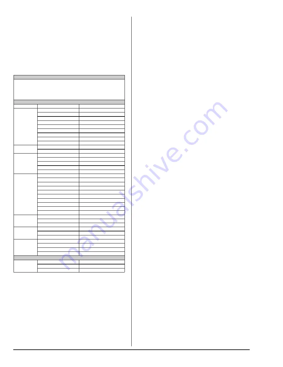
MACHINE INFO
Coin Vault:
$0.00
Upper Hours:
0
Lower Hours:
0
Serial #:
1000000
Software:
R3-3.0
PROGRAM SETUP
Dry Mode
Coin / Free Dry Mode
Coin Dry Mode
CONTROL
SETTINGS
Language
Multilanguage
Off
Language 1
English
Language 2
French
Temp Scale °F / °C
°F
Buzzer Settings
End of Cycle
On
Beep Count
(1 - 10)
Backlighting
(0 - 200)
MACHINE
SETTINGS
Lint Cleaning Freq
(1 - 3 Hours)
Axial Max Temp
(100° - 180° F / 32° - 82° C)
KEY
SETTINGS
Time for Amt to Start
(1 - 99 Minutes)
Time for Top Off
(1 - 99 Minutes)
Dry Temp
(100 - 160F)
Cool Time
(0 - 9 Minutes)
Reversing Mode
(Off / On)
VENDING
OPTIONS
Currency Symbol
$ GBP Euro Yen Tk
Vending Mode
ACC Time ACC Coin
Vending Safe Guard
Bad Coin Reset / Lo
Clear Escrow
(0 - 99 Minutes)
Clear Coin Vault?
No / Yes
Left Coin Value
($0.01 - $25.00)
Right Coin Value
($0.01 - $25.00)
Amount to Start
($0.01 - $25.00)
Amount for Top Off
($0.01 - $25.00)
Debit Card Setup
Off Gen 1 Gen 2
DIAGNOSTIC
MODE
Fault Recording
Faults / Events
Diagnostic Cycle
Select Cycle
Help Mode
MACHINE
SETUP
Model
Gas Ele Steam Rev/Non-Rev
Dryer Type
Coin / Free or OPL
Burner Setup
1, 2 Not Available on Stack
AVAILABLE
ONLY ON
REV 2.3
AND UP
Residual Moisture Control
Off, On
RMC Temp
(90° - 160° F / 32° - 71° C)
RMC Factor
(50 - 300)
Rotation Sensor
Off / On
DIAGNOSTIC MODE
FAULT
RECORDS
Upper Faults
Non-Resettable
Lower Faults
Non-Resettable
Events
E1 - E8 Resettable
Programming _________________________
Enter Service Mode by Inserting Key and Turning Clockwise
Main Service Mode window will appear and offer 5 selections:
1: Machine Info
2: Program Setup
3: Diagnostic Mode
4: Machine Setup
5: Factory Settings
Low Key
Scroll Down / Decrease Value
High Key
Scroll Up / Increase Value
Med Key
Accept Value or Menu Selection
Pause II
Cancel Selection or Back Out of the Menu
Event Codes Defined: Top Pocket / Bottom
E1 / E4: While attempting to turn on the burner, no burner return
signal was received within RADIANT SENSOR COOL DOWN
TIME.
E2 / E5: While trying to turn on burner, burner return signal
received but did not disappear within HEAT IGNITION TIMEOUT
TIME.
E3 / E6: While attempting to activate the heat relay, no heat
relay contact voltage was detected. This will indicate that either
the exhaust high limit was open or that the relay is damaged.
E7: This indicates a bad coin pulse was detected on coin 1 input.
E8: This indicates a bad coin pulse was detected on coin 2 input.
E9 / EB: Upper / Lower forward pocket rotation fault count.
EA / EC: Upper / Lower reverse rotation fault count.
ED: S.A.F.E. DISABLED – Water not connected.
Factory Settings Definitions:
RADIANT TIMEOUT – During an attempt to start the burner this
parameter sets the maximum wait time for the radiant sensor to
cool and close circuit. A failure causes an E1 or E4 event and a
heat disable period specified by the HEAT DISABLE parameter
setting.
IGNITER TIMEOUT – During an attempt to start the burner this
parameter sets the maximum wait time for the radiant sensor to
heat and open circuit. A failure causes an E2 or E5 event and a
heat disable period specified by the HEAT DISABLE parameter
setting.
HEAT DISABLE – The wait time after a RADIANT or IGNITOR
TIMEOUT before another attempt to start the burner is made.
Help Codes Defined: Top Pocket / Bottom
86 / 81 Exhaust Probe Fault – Open or shorted exhaust probe.
87 / 82 Axial Probe Fault – Open or shorted axial probe.
89 / 84 Sail Switch Open Fault – Air flow failure.
88 / 83 Sail Switch Closed Fault – Sail Switch stuck or disabled.
Fault Messages Defined:
LATCHED HEAT RELAY – Heat signal present without PH8
command.
BURNER RTN VOLTAGE – Heat return signal without PH8 heat
output.
ROTATION SENSOR – No tumbler rotation signal during a cycle.
EXHAUST HIGH TEMP – Exh temp 20F above highest settable
temp.
BLOCKED COIN – Coin optic blocked or an open coin drop
circuit.
CARD READER NO COMM – No messages received from the
Gen II card reader for 5 minutes or more.
Clear Faults:
In SERVICE MODE entering the diagnostic mode menu will clear
the operational fault. Clearing faults from the fault record is not
allowed.
Clear Credit:
While machine is idle displaying “SELECT A CYCLE” press and
hold PAUSE, while holding PAUSE press HI, HI, HI, LO, LO,
MED within 3-seconds and the control will display “CLEAR
CREDIT?” While still holding PAUSE press any key to clear
credit. Releasing PAUSE then pressing any key will not clear
credit.
Diagnostic Cycle
After selecting DIAGNOSTIC MODE the HI, MED or LOW key is
used to start a dry cycle. The HI is used to increase the dry
time. The MED key will stop the cycle. DEL toggles the HELP
SCREEN.
Help Mode
Selecting the HELP MODE displays the HELP SCREEN. In
HELP MODE the HI key will step the highlighted area through all
monitored inputs and provide more detail.
Machine setup is password protected and password is med or
pause key four times.
Содержание ES3131
Страница 26: ...ADC Part No 113280 3 11 26 14 ...


