background image

20

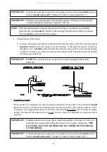
3. Grounding

A ground (earth) connection 

must be

 provided and installed in accordance with state and local codes.  In

the absence of these codes, grounding 

must conform

 to applicable requirements of the National Electrical

Code ANSI/NFPA NO. 70-LATEST EDITION, or in Canada, the Canadian Electrical Codes Parts 1 & 2

CSA C22.1-1990 or LATEST EDITION.  The ground connection may be to a proven earth ground at the

location service panel.

For added personal safety, when possible, it is suggested that a separate ground wire (no. 18 minimum) be

connected from the ground connection of the dryer to a grounded cold water pipe.  

DO NOT ground to a

gas pipe or hot water pipe

.  The grounded cold water pipe must have metal to metal connection 

ALL

 the

way to the electrical ground.  If there are any nonmetallic interruptions, such as, a meter, pump, plastic,

rubber, or other insulating connectors, they 

must be

 jumped out with no. 4 copper wire and securely

clamped to bare metal at both ends.

IMPORTANT:

For personal safety and proper operation, the dryer


must be

 grounded.

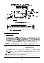
Provisions are made for ground connection in each dryer at the electrical service connection area.

4. Electrical Connections

NOTE:

A wire diagram is located in the front electrical control box for connection data.

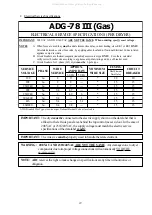
a. Gas Models

NOTE: A CIRCUIT SERVICING EACH DRYER 

MUST BE

 PROVIDED

.

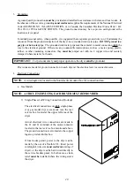
1) Single-Phase (1ø) Wiring Connections (Hookup)

The electrical connections on 

ALL

 single-phase

(1ø)  gas  model  dryers  are  made  into  the  rear

service box located at the upper left area of the

dryer.

Actual electrical wire connections are made to

the L1 and L2 terminals of the motor contactor

located in the rear service box mentioned above.

The ground connection is also made to the copper

lug also provided in this box.

If local codes permit, power to the dryer can be

made by the use of a flexible U.L. listed power

cord/pigtail (wire size 

must conform

 to rating of

dryer), or the dryer can be hard wired directly to

the service breaker panel.  In both cases, a strain

relief 

must be

 installed where the wiring enters

the dryer.

All manuals and user guides at all-guides.com

Содержание AD-78III

Страница 1: ...the fire department Installation and service must be performed by a qualified installer service agency or the gas supplier AVERTISSEMENT Assurez vous de bien suivre les instructions donn es dans cette...

Страница 2: ...possible and hope you will find it useful ADC reserves the right to make changes from time to time without notice or obligation in prices specifications colors and material and to change or discontinu...

Страница 3: ...HOULD NEVER BE LEFT UNATTENDED WHILE IN OPERATION CAUTION FOR YOUR SAFETY DO NOT DRY MOP HEADS IN THE DRYER DO NOT USE DRYER IN THE PRESENCE OF DRY CLEANING FUMES WARNING UNDER NO CIRCUMSTANCES should...

Страница 4: ...d or specified in the installation manual included with the dryer Dryers must not be installed or stored in an area where itwill be exposed to water or weather The wiring diagram for the dryer is loca...

Страница 5: ...esh Air Supply Requirements 14 E Exhaust Requirements 15 F Electrical Information 18 G Gas Information 24 H Preparation For Operation Start Up 28 I Preoperational Tests 29 J Preoperational Instruction...

Страница 6: ...N 38 A Data Label 38 SECTION IX PROCEDURE FOR FUNCTIONAL CHECK OF REPLACEMENT COMPONENTS 40 SECTION X BURNER AND BASKET TUMBLER LINT CHAMBER MANUAL RESET HI LIMIT INSTRUCTIONS 42 Phase 7 Models 42 Dua...

Страница 7: ...ceived and the number refused must be noted on the receipt 4 If you determine that the dryer was damaged after the trucker has left your location you should call the delivering carrier s freight termi...

Страница 8: ...er from a neighbor s phone Follow the gas supplier s instructions f If you cannot reach your gas supplier call the fire department 4 Installation and service must be performed by a qualified installer...

Страница 9: ...h or heat safety circuit ever be disabled WARNING PERSONALINJURYOR FIRE COULD RESULT 10 This dryer is not to be used in the presence of dry cleaning solvents or fumes 11 Remove articles from the dryer...

Страница 10: ...ceor obligation Gas MAXIMUM CAPACITY DRY WEIGHT 75 lbs 34 kg BASKET TUMBLER DIAMETER 44 1 2 113 03 cm BASKET TUMBLER DEPTH 24 7 8 63 18 cm BASKET TUMBLER VOLUME 22 4 cu ft 0 634 cu m BASKET TUMBLER MO...

Страница 11: ...7 Specifications ADG 78 III Gas NOTE ADCreservestherighttomakechangesinspecificationsatanytimewithoutnoticeor obligation All manuals and user guides at all guides com a l l g u i d e s c o m...

Страница 12: ...ontrols 2 Control top access Door Assembly 3 Main DoorAssembly 4 Lint Compartment Area lint screen located behind door 5 Data Label and Installation Label affixed to the left side panel area behind th...

Страница 13: ...4 Basket tumbler Bearing Mount Assembly 5 Idler Bearing MountAssembly 6 Basket drive Motor Assembly for reversing models only 7 Leveling Leg rear 8 Blower Motor Assembly 9 Dryer Exhaust Electric serv...

Страница 14: ...st be installed on a sound level floor capable of supporting its weight Carpeting must be removed from the floor area that the dryer is to rest on IMPORTANT Thedryermustbeinstalledonnoncombustiblefloo...

Страница 15: ...emove the two 2 bolts located in the lint chamber area remove the lint door With the skid removed to make it easier to slide the dryer into its final position slightly lower ALL four 4 leveling legs s...

Страница 16: ...e illustration below d Remove the two 2 self tapping screws on the back electrical box and pull through ALL associated wires from the motor to this electrical box refer to the illustration below e Rev...

Страница 17: ...ance must be made for the opening and closing of the control door and the lint door It is suggested that the dryer be positioned about 2 feet 0 61 meters away from the nearest obstruction for ease of...

Страница 18: ...n and make up air supply To compensate for the use of registers or louvers used over the openings this make up air must be increased by approximately thirty three percent 33 Make up air openings shoul...

Страница 19: ...side protection from the weather no more than two 2 elbows should be used in the exhaust duct run If more than two 2 elbows are used the cross sectional area of the ductwork must be increased ALL duct...

Страница 20: ...ce the diameter of the duct between the duct opening and the nearest obstruction IMPORTANT DO NOT use screens louvers or caps on the outside opening of the exhaust ductwork 2 Single Dryer Venting Wher...

Страница 21: ...escaping into the building Inspection doors should be installed at strategic points in the exhaust ductwork for periodic inspection and cleaning of lint from the ductwork NOTE Whentheexhaustductworkp...

Страница 22: ...SA C22 1 1990 or LATEST EDITION IMPORTANT Failuretocomplywiththesecodesorordinances and ortherequirementsstipulated inthismanualcanresultinpersonalinjuryorcomponentfailure NOTE Componentfailureduetoim...

Страница 23: ...AC ARE NOT THE SAME When ordering specify exact voltage When fuses are used they must be dual element time delay current limiting class RK1 or RK5 ONLY Calculate determine correct fuse value by applyi...

Страница 24: ...mped to bare metal at both ends IMPORTANT For personal safety and proper operation the dryer must be grounded Provisions are made for ground connection in each dryer at the electrical service connecti...

Страница 25: ...per rear area of the dryer NOTE ACIRCUIT SERVICINGEACH DRYER MUST BE PROVIDED If local codes permit power to a gas dryer can be made by the use of a flexible U L listed power cord pigtail wire size mu...

Страница 26: ...is required on a 3 phase 3 dryer For gas dryers manufactured for operation at 3 phase 3 the electrical connections are made at the power distribution block located in the service box at the rear upper...

Страница 27: ...to the service breaker panel In ALL cases a strain relief must be installed where the wiring enters the dryer The only electrical input connections to the dryer are the 3 phase 3 power leads L1 L2 L3...

Страница 28: ...chwillVOIDTHEWARRANTY WARNING FIRE OR EXPLOSION COULD RESULT 1 Gas Supply The gas dryer installation must meet the American National Standard National Fuel Gas Code ANSI Z223 1 LATESTEDITION or in Can...

Страница 29: ...26 1 mb water column There is no regulator or regulation provided in an L P dryer The water column pressure must be regulated at the source L P tank or an external regulator must be added to each dry...

Страница 30: ...d The dryer is provided with a 3 4 N P T inlet pipe connection located at the right side of the base of the dryer The minimum pipe size supply line to the dryer is 3 4 N P T For ease in servicing the...

Страница 31: ...hingonasoapywatersolution liquid detergentworkswell WARNING NEVER TEST FOR LEAKS WITHAFLAME ALL components materials must conform to National Fuel Gas Code SpecificationsANSI Z223 1 LATEST EDITION or...

Страница 32: ...ryer data label 4 GAS MODELS the sail switch damper assembly was installed and adjusted at the factory prior to shipping However each sail switch adjustment must be checked to assure that this importa...

Страница 33: ...shutoffvalvesareopen NOTE GasdryersareequippedwithaHotSurfaceIgnition HSI system whichhasinternal diagnostics Ifignitionisnotestablishedwithinthefirstattempt theheatcircuitintheHSI modulewill LOCKOUT...

Страница 34: ...ges are required refer to the computer programming manual which was shipped with the dryer 6 Check the electric service phase sequence 3 phase 3 models only While the dryer is operating check to see i...

Страница 35: ...ing instructions b Dual Timer Dryers 1 Turn drying timer knob for a time of 20 minutes 2 Select High Temp 3 Push Start button 4 To stop dryer open the main door K SHUT DOWN INSTRUCTIONS If the dryer i...

Страница 36: ...ndledinanexpeditiousmanner B PARTS 1 Replacement parts should be purchased from the reseller from whom the ADC equipment was purchased If the reseller cannot be contacted or is unknown contact the ADC...

Страница 37: ...e equipment and request a dryer warranty form If the reseller cannot be contacted or is unknown warranty information can be obtained from the factory by contacting the ADC Warranty Department at 508 6...

Страница 38: ...claims are the responsibility of the shipper IMPORTANT No replacements credits or refunds will beissued for merchandise damaged in transit 5 ALL returns should be shipped to the ADC factory in such a...

Страница 39: ...AND LIQUIDS NOTE Suggestedtimeintervalsshownareforaverageusagewhichisconsideredsix 6 toeight 8 operational running hoursperday IMPORTANT Dryer produces combustible lint and must be exhausted to the o...

Страница 40: ...cesisrecommended B ADJUSTMENTS 7 DAYS AFTER INSTALLATION AND EVERY 6 MONTHS THEREAFTER Inspect bolts nuts screws bearing setscrews grounding connections and nonpermanent gas connections unions shutoff...

Страница 41: ...the basket tumbler Spin Time are adjustable by mode selection switches located on the electronic timer as noted in the illustration below TIMING LEGEND SPIN TIME Adjustment Position Number 1 2 3 4 5 T...

Страница 42: ...uired to insure proper service parts information from ADC This information is on the data label that is affixed to the left side panel area behind the top control access door When contacting ADC pleas...

Страница 43: ...OF HEAT This describes the type of heat for your particular dryer gas either natural gas or liquid propane L P gas or steam 5 HEAT INPUT for GAS DRYERS This describes the heat input in British Therma...

Страница 44: ...lacement microprocessor controller computer board reestablish power to the dryer b Start the drying cycle by pressing any of the preset cycles in letters A F c Verify that the applicable indicator lig...

Страница 45: ...blished e With the burner flame on remove the flame sensor wire from the S2 terminal of the HSI module The burner flame must shut off immediately f Stop the drying cycle with the flame sensor wire sti...

Страница 46: ...ng with an audio indication If the drum temperature is above 100 F 38 C the dryer will continue to run with no heat for 3 minutes or until the drum temperature has dropped below 100 F 38 C The clear s...

Страница 47: ...hrough the drying cycle with no heat Manual reset hi limit thermostat must be reset manually This hi temperature condition may be caused due to a restricted exhaust poor airflow or improper burner ove...

Страница 48: ...ADC113340 1 08 28 01 15 2 09 27 01 25 3 03 25 02 25 All manuals and user guides at all guides com...

Отзывы: