


Installation
150-204-100-03, Issue 3
8
May 7, 1999
HRE-204 List 1 and List 2
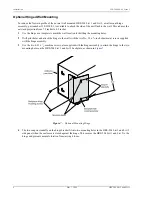
Optional Hinged Wall Mounting
To reduce the forward profile of the normal wall mounted HRE-204 List 1 and List 2, a wall mount hinge
assembly, part number 150-2224-01, is available to attach the side of the unit flush to the wall. This reduces the
outward projection from 7.5 inches to 4.8 inches.
1
Use the hinge as a template to mark the wall location for drilling the mounting holes.
2
Drill pilot holes and attach the hinge to the wall with the two No. 10 x
5
/
8
-inch sheet metal screws supplied
with the hinge assembly.
3
Use the two 6-32 x
1
/
4
machine screws, also supplied with the hinge assembly to attach the hinge to the two
mounting holes on the HRE-204 List 1 and List 2 backplate, as shown in
Figure 7.
Optional Mounting Hinge
4
The two snap-in standoffs on the hinge bracket fit into two mounting holes in the HRE-204 List 1 and List 2
side panel when the enclosure is closed against the hinge. This secures the HRE-204 List 1 and List 2 to the
hinge and prevents normal vibration from jarring it loose.