Section 100-427-100 Revision 04
14 of 16
Page
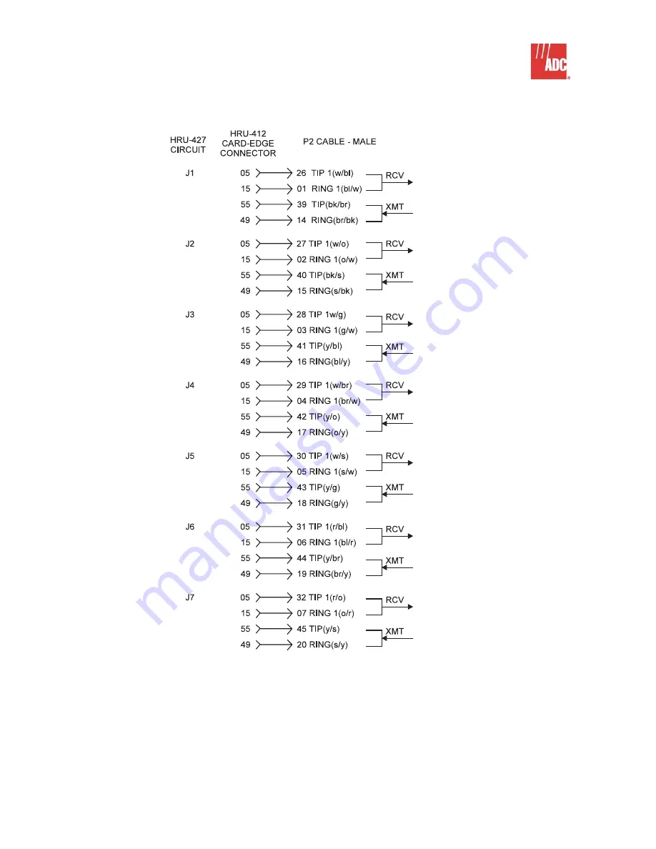
Figure 9. T1 USOC RJ-48H Connector (P2).
To use this interface, remove the RJ-48C cable assembly
attached to P2 and insert a mating cable with a female connector in its place.
Страница 1: ...ND FEATURES 2 2 SPECIFICATIONS 3 3 WARRANTY 4 4 TECHNICAL SUPPORT 4 B INSTALLATION 5 5 MOUNTING OPTIONS 5 6 WIRING 8 7 TURN UP 15 Revision History Revision 03 October 25 1996 a Updated Figures 5 throu...
Страница 2: ...1 inside the enclosure connects the remote units to HDSL loops 1 and 2 via a customer supplied 25 pair type 57 cable through a cable access hole on the left side of the enclosure The enclosure has fou...
Страница 3: ...ular jacks List 2 seven RJ 48X modular jacks List 1 or 2 one T1 USOC RJ 48H connector P2 Local Power Supply slot 8 120V ac to 48V dc 2A 2 5A 400 Type mechanics HPS 448 L1 Fusing 1 4A protection for ea...
Страница 4: ...DC for repair Any modifications of the unit by anyone other than an authorized ADC representative will void the warranty 3 03 If a unit needs repair call ADC for a Return Material Authorization RMA an...
Страница 5: ...he transportation company and to ADC The following items are supplied in the installation kit Two security keys One pin head security wrench One lock replacement plug Four mounting screws and washers...
Страница 6: ...page 8 4 Slide the backplate down until the locking pins are in position to clear the retaining slots and then remove the backplate from the main assembly 5 Using the backplate or enclosed drawing as...
Страница 7: ...lock Remove the lever 3 Using a wrench loosen and remove the 7 8 inch hex nut holding the lock to the top cover 4 Remove the lock from the top cover and plug the hole with the plastic plug supplied wi...
Страница 8: ...ng option changes may require future access to the connector pins of the enclosure s remote units be sure to allow a sufficient service loop in cables to remove the unit from the back plate wall mount...
Страница 9: ...are limited to a 30 volt maximum output level and as such cannot power some CSUs which require 60 mA at 60V However the 30V output level is more than adequate to power all external smart jacks NIU Set...
Страница 10: ...tory Testing Do Not Use CI CURRENT I OPTIONS CURRENT 0 mA 23 mA 60 mA SWITCH A OFF down ON up ON up CI CURRENT I OPTIONS CURRENT 0 mA 23 mA 60 mA SWITCH B OFF down OFF down ON up 1 1 2 2 1 XMT and RCV...
Страница 11: ...e that if you reverse these leads a CHREV message is displayed in the ALARMS display field when you view the HRU STATUS screen from either HiGain terminal interface port HLU or HRU This condition does...
Страница 12: ...gnostic and status monitoring terminal to the front panel of some remote units Similar access to other units is available by direct wire wrap access to pins 37 and 38 of each unit s card connector whi...
Страница 13: ...Section 10 427 100 Revision 04 Page 13 of 16 Figure 8 List 2 RJ 48X Pin Assignment The RJ 48X jacks are located on the left side of the List 2 enclosure...
Страница 14: ...100 427 100 Revision 04 14 of 16 Page Figure 9 T1 USOC RJ 48H Connector P2 To use this interface remove the RJ 48C cable assembly attached to P2 and insert a mating cable with a female connector in it...
Страница 15: ...Section 10 427 100 Revision 04 15 of 16 Page 7 TURN UP 7 01 Refer to the appropriate user manual for proper turn up procedures Figure 10 48V Local Power Option Connections...
Страница 16: ...n contained in this document is company private to ADC Telecommunications Inc and shall not be modified used copied reproduced or disclosed in whole or in part without the written consent of ADC Conte...